
Fig 1502 is a principal high-pressure hammer union connection used in hydraulic fracturing and other demanding flow iron systems. Correct selection requires more than the figure number alone: nominal size, bore, end connection, seal system, service class and controlled dimensions must all match the intended assembly.
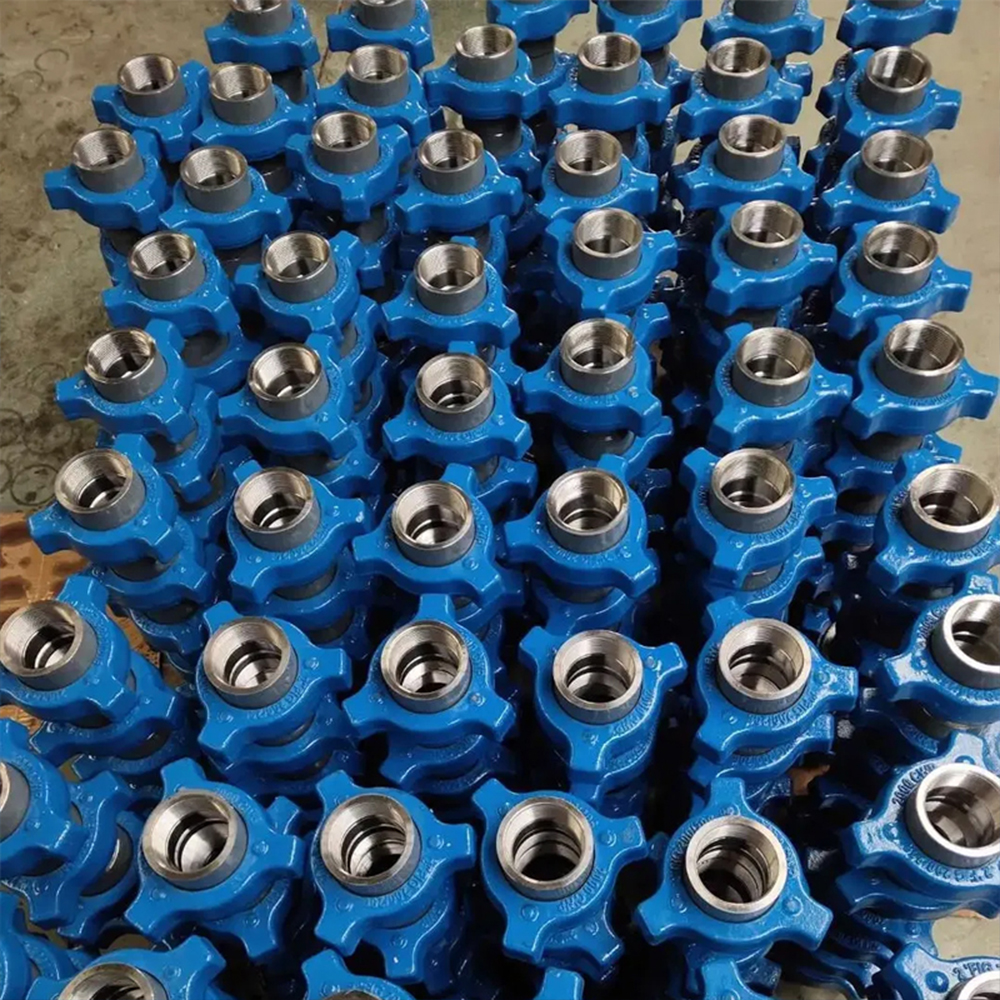
Quick Answer: What Is a Fig 1502 Hammer Union?
A Fig 1502 hammer union is a high-pressure, quick-makeup flow iron connection used to join pressure-containing components without rotating the connected pipe. GPE identifies Fig 1502 with a 15,000 psi pressure reference for hydraulic fracturing and high-pressure flow iron. A complete assembly uses a matched male sub, female sub, wing nut and figure-specific high-pressure seal. Final selection must still confirm the nominal size, bore, end geometry, material, temperature, fluid, service class and approved dimensional drawing.
Need to Match an Existing Fig 1502 Connection?
Send GPE the figure, nominal size, working pressure, threaded or butt-weld end, service condition and quantity. If you have an existing drawing, part number or measured dimensions, include them for faster engineering review.
What Is a Fig 1502 Hammer Union?
A hammer union is designed to create a rapid mechanical connection between two pressure-containing flowline components. The connected pipe or valve does not have to rotate during makeup or breakout. Instead, the wing nut draws the matched male and female subs together and loads the sealing interface.
Within GPE’s published hammer union range, Fig 1502 is the principal 15,000 psi connection for hydraulic fracturing and high-pressure flow iron. It is used where a compact, serviceable connection is required between equipment such as frac pump discharge piping, rigid straight pipe, plug valves, check valves, swivel joints and manifold components.
However, “Fig 1502” is not a complete purchase specification. Figure number identifies a pressure and geometry family, but the final connection must also match size, bore, end type, seal profile, material and service condition.
Why Fig 1502 Is Used
High-pressure pumping systems require connections that can be assembled and serviced efficiently while maintaining a controlled pressure interface. A hammer union provides a compact connection without requiring the adjoining pipe to rotate.
What Must Match
Figure, nominal size, pressure class, bore, ACME thread geometry, male/female interface, seal profile and service class must be treated as one matched connection system.
Fig 1502 Hammer Union Pressure Rating
GPE publishes Fig 1502 with a 15,000 psi pressure reference for hydraulic fracturing and high-pressure flow iron service. This figure-level rating is useful for system identification, but it should never be treated as the only design or purchasing criterion.
Pressure Selection Requires More Than “15K”
Before ordering a Fig 1502 union, the buyer should confirm the normal and maximum operating pressure of the complete line and compare it with the rating of every connected component. The system is limited by its lowest-rated pressure-containing component.
| Selection Item | Why It Matters | What to Confirm |
|---|---|---|
| Working pressure | Defines the required pressure class of the connection and the complete flowline. | Normal pressure, maximum pressure and project design basis. |
| Nominal size and bore | Controls the flow passage and must match the connected equipment. | Nominal connection size and required internal bore. |
| End configuration | A threaded sub and a butt-weld sub require different external geometry. | Thread specification or pipe OD, wall and weld preparation. |
| Fluid and proppant | Abrasive or corrosive service can affect material, seal and inspection requirements. | Fluid type, solids/proppant and chemistry where applicable. |
| Temperature and service class | Material and elastomer selection must suit the operating environment. | Temperature range and Standard, Low-Temperature or H₂S service requirement. |
Fig 1502 Hammer Union Dimensions: What Must Be Checked?
There is no responsible way to select a replacement Fig 1502 connection from the figure number and nominal size alone. Exact dimensions are controlled by the approved drawing for the specific size, bore, end connection and service configuration.
For this reason, GPE does not recommend treating an uncontrolled internet dimension chart as a universal replacement standard. When matching an existing union, use the controlled drawing, permanent marking, part number, measured component geometry or a verified physical sample.
Key Dimensions on a Fig 1502 Drawing
| Drawing Item | Typical Meaning | Why Buyers Should Verify It |
|---|---|---|
| Nominal connection size | Specified union size for the connected system. | Must match the adjoining valve, pup joint, swivel or manifold port. |
| Flow bore / ID | Internal flow passage through the pressure connection. | A mismatch can create an unwanted restriction or mechanical interference. |
| Overall length | End-to-end assembly envelope. | Critical when replacing a union in an existing rigid layout. |
| Wing nut OD and lug envelope | Outside envelope of the operating nut. | Determines access and clearance around adjacent equipment. |
| Male nose / female seat geometry | Pressure interface between the two matched subs. | Must match the approved figure-specific sealing geometry. |
| ACME thread geometry | Wing-nut engagement geometry. | Visual similarity is not proof of compatibility. |
| Threaded-end details | Thread form, size, orientation and gauge requirement. | Required when the union connects to threaded equipment. |
| Butt-weld-end details | Pipe OD, bore, wall thickness and weld preparation. | Required for weld-integrated flowline fabrication. |
| Seal groove / seal interface | Geometry controlling the high-pressure seal. | Must correspond to the approved Fig 1502 seal arrangement. |
How to Read a Fig 1502 Hammer Union Drawing
A useful engineering drawing should do more than show overall length. It should identify the pressure interface and all dimensions that control whether the union will physically and functionally match the connected equipment.
1. Start With the Figure and Size
Verify the permanent Fig 1502 identification and the nominal size before comparing external dimensions.
2. Check the Bore
Confirm the controlled flow bore and ensure it matches the intended system arrangement.
3. Check the End Connection
Identify threaded, butt-weld or another approved external end configuration.
4. Verify the Seal Interface
Do not assume a replacement seal or sub is compatible because the parts look similar.
5. Confirm Assembly Envelope
Overall length and nut clearance matter when the union is installed between fixed components.
6. Review Service Marking
Pressure and service class should be verified from controlled identification, not paint color alone.
2-Inch, 3-Inch and 4-Inch Fig 1502 Requests: What Changes?
Buyers often identify a hammer union by nominal size, for example “2-inch Fig 1502.” The nominal size is essential, but it still does not define the complete union. Each size request should be accompanied by the required bore, end configuration and service data.
2-Inch Fig 1502 Request
State the 2-inch nominal size, required working pressure, bore, threaded or butt-weld end, service condition and whether you need a complete assembly or replacement component.
3-Inch Fig 1502 Request
Confirm the same connection data and include the adjoining valve, pup joint, swivel or manifold interface when dimensional matching is required.
4-Inch Fig 1502 Request
Large connection requests should be reviewed against the approved drawing, required bore, wall/end geometry and complete system pressure specification.
Size-specific availability and dimensions should be confirmed against the current GPE approved drawing and project configuration before purchase.
Threaded vs Butt-Weld Fig 1502 Hammer Unions
GPE supplies high-pressure hammer unions with threaded and butt-weld end configurations. The union interface performs the quick connection, while the external end determines how the union sub connects to the adjoining pipe or equipment.
| Item | Threaded Fig 1502 | Butt-Weld Fig 1502 |
|---|---|---|
| External connection | Approved thread form and orientation | Weld end matched to specified pipe geometry |
| Data required | Thread specification, size and pin/box orientation where applicable | Pipe OD, bore, wall thickness, material and weld preparation |
| Typical procurement focus | Thread compatibility and gauge confirmation | Pipe compatibility, weld preparation and fabrication drawing |
| Replacement check | Thread + figure + seal geometry + service class | Pipe geometry + figure + seal geometry + service class |
When requesting a replacement union, a description such as “Fig 1502 threaded” is still incomplete. The GPE engineering team should receive enough information to verify both the union interface and the external equipment connection.
Buying for an Existing Flowline?
Do not match only by color or outside appearance. Send the existing marking, figure, nominal size, connection type, seal information and drawing or measured dimensions for review.
Fig 1502 Hammer Union Components
A complete Fig 1502 hammer union should be treated as a matched pressure connection rather than a collection of visually similar spare parts.
| Component | Function | Selection Check |
|---|---|---|
| Male Sub | Forms one side of the pressure interface and contains the male sealing nose, flow bore and external connection. | Figure, size, bore, nose geometry, end configuration and service class. |
| Female Sub | Receives the male sub and contains the matching seat or seal region and wing-nut thread interface. | Figure, size, seat/seal geometry, bore and external connection. |
| Wing Nut | Draws the two subs together and provides the approved impact lugs for makeup and breakout. | Correct figure, ACME thread geometry, condition and matching sub set. |
| Seal System | Provides the figure-specific high-pressure sealing interface. | Correct figure, size, profile, material/service requirement and condition. |
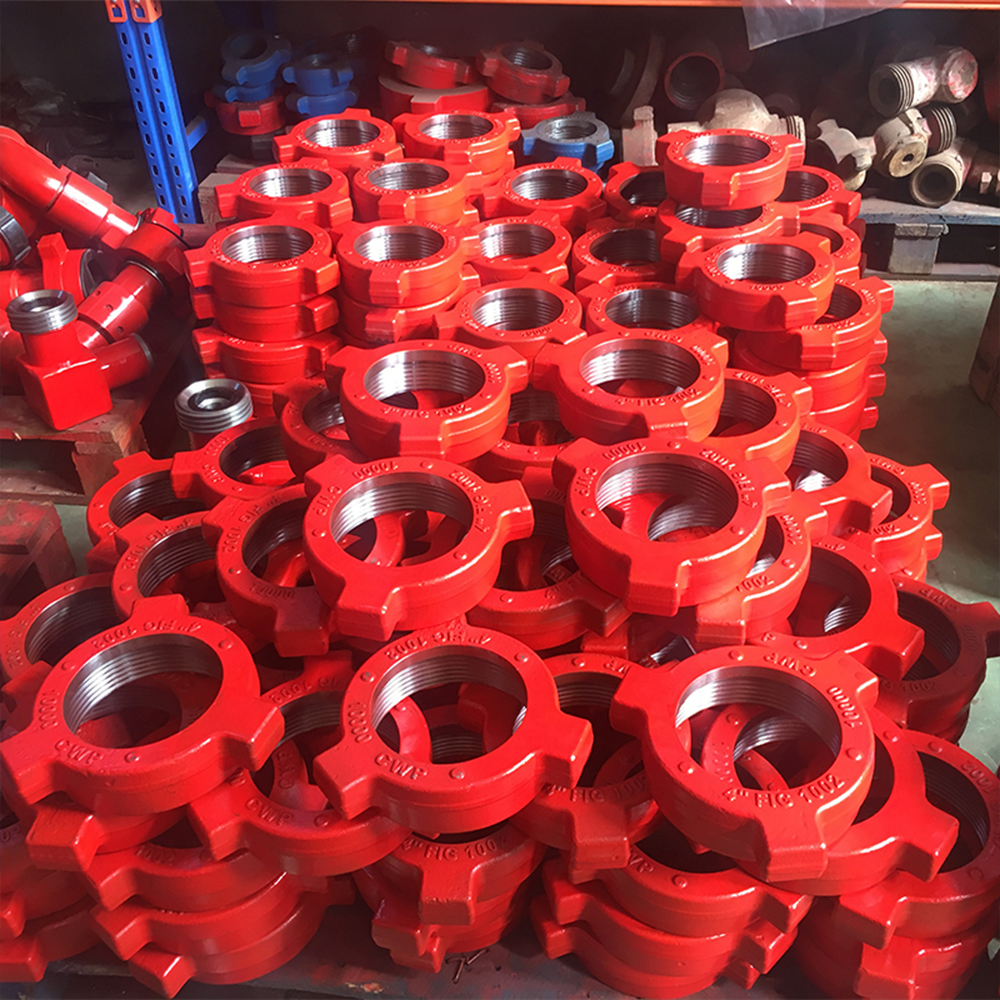
GPE hammer union components are selected as figure-, size- and service-specific pressure connection parts.
Fig 1502 Hammer Union Seal: Why the Exact Match Matters
The seal system is part of the pressure boundary. GPE describes Fig 1502 as using a high-pressure replaceable seal ring, but replacement selection should still be based on the exact figure, size, seal profile and service requirement.
A replacement seal should not be selected from color or approximate dimensions alone. Inspect the sealing surfaces and groove, verify the original connection identification, and confirm whether the union is intended for Standard, Low-Temperature or H₂S service.
GPE supplies figure-specific seal rings, O-rings, pressure seals and service parts together with complete hammer union assemblies.
Where Is Fig 1502 Used in a Frac Iron System?
Fig 1502 connections are commonly positioned between high-pressure components that must be rigged up, removed or serviced as part of a temporary or skid-mounted pressure-pumping line. Within GPE’s frac iron product family, the connection can be integrated with rigid straight pipe, plug valves, check valves, swivel joints and manifolds.
The exact sequence varies by spread layout and operating philosophy. The important engineering point is that the hammer union must match the pressure class, bore and connection geometry of the components on both sides.
Fig 602 vs Fig 1002 vs Fig 1502
Hammer union figure numbers represent different pressure and sealing families. They should not be treated as interchangeable labels.
| Figure | GPE Pressure Reference | Published Configuration | Typical GPE Service Positioning |
|---|---|---|---|
| Fig 602 | 6,000 psi | Replaceable resilient seal ring | Cementing and circulation |
| Fig 1002 | 10,000 psi | Replaceable high-pressure seal | Cementing, acidizing and testing |
| Fig 1502 | 15,000 psi | High-pressure replaceable seal ring | Hydraulic fracturing and high-pressure flow iron |
How to Select a Fig 1502 Hammer Union
A useful purchase specification should describe the complete connection rather than simply stating “1502 hammer union.” GPE recommends the following selection sequence.
1. Confirm the Required Figure
Verify that Fig 1502 is the required connection family from the existing equipment drawing, permanent product marking or new system design.
2. Confirm the Nominal Size and Bore
State the required nominal size and, where needed, the controlled flow bore. Do not assume that nominal size alone defines every internal dimension.
3. Define Normal and Maximum Working Pressure
Provide the operating pressure basis for the complete line and confirm that connected valves, pipe, swivels and manifolds meet the system requirement.
4. Select Threaded or Butt-Weld Ends
For threaded connections, provide the thread specification and orientation. For butt-weld connections, provide pipe OD, bore, wall thickness, material and weld preparation.
5. Identify the Service Fluid
State whether the connection will handle fracturing fluid, proppant-bearing slurry, cement, acid, test fluid, flowback or another medium. Include relevant corrosive constituents where applicable.
6. Confirm Temperature and Service Class
Specify the operating temperature range and whether Standard, Low-Temperature or H₂S service is required. These items affect material and seal selection.
7. Specify Complete Assembly or Spare Component
Indicate whether you require a complete union, male sub, female sub, wing nut, seal, blind component or repair kit.
8. Provide Existing Connection Data for Replacement Work
Include drawings, part numbers, permanent markings, measured dimensions or physical sample data when the new union must match an installed flowline.
9. Define Inspection, Testing and Documentation
State any project requirements for material certificates, NDE, hardness inspection, dimensional inspection, pressure testing, traceability and final documentation.
10. Confirm Quantity and Delivery Requirement
Provide quantity, destination and requested delivery date so the quotation can include the correct manufacturing and export scope.
Manufacturing, Inspection and Pressure Testing
For high-pressure hammer union production, connection performance depends on the complete chain from material control through machining and pressure testing. GPE’s published manufacturing process includes material-certificate verification, heat-number identification, controlled forging and heat treatment, CNC machining, dimensional inspection and permanent marking.
Pressure-Body Control
Forged pressure components are produced and heat treated under a controlled manufacturing plan, with the figure-specific geometry machined to the approved drawing.
Connection Inspection
Bore, sealing surfaces, seal grooves, ACME threads and external end connections are inspected according to the applicable manufacturing and project requirements.
NDE and Hardness
Specified UT, MPI, hardness and dimensional checks are applied according to the approved inspection plan and service requirement.
Hydrostatic Test
Hammer unions receive figure-specific hydrostatic pressure testing as part of the controlled product verification process.
Connection Compatibility and Field Safety
High-pressure union connections should never be matched by paint color or external appearance alone. A safe assembly requires the correct figure, size, pressure geometry, ACME thread, seal interface, bore and service class.
- Never strike, tighten, loosen or dismantle a pressurized hammer union.
- Never exceed the marked working pressure or the lowest-rated component in the system.
- Never mix different hammer union figures.
- Never mix Standard and H₂S service components without formal engineering verification.
- Never force damaged or mismatched threads into engagement.
- Do not use color as the only identification method.
- Do not use a hammer union as a lifting or suspension point.
Information to Send for a Fig 1502 Hammer Union Quote
The fastest way to receive a useful technical quotation is to send the connection and service information at the beginning of the inquiry.
- Figure number
- Nominal size
- Normal working pressure
- Maximum working pressure
- Required flow bore
- Threaded or butt-weld construction
- Thread specification and orientation
- Pipe OD, bore and wall thickness for butt-weld ends
- Male, female, blind or complete assembly
- Service fluid
- Proppant or solids information
- Operating temperature
- Standard, low-temperature or H₂S service
- Existing drawing or part number
- Measured dimensions or sample data
- Inspection requirement
- Pressure-testing requirement
- Documentation and traceability requirement
- Quantity
- Destination and requested delivery date
Request a Fig 1502 Hammer Union Drawing and Quotation
GPE manufactures high-pressure hammer unions and related flow iron components for fracturing, cementing, testing and pressure-pumping systems. Send your project data or existing connection drawing so our team can review the figure, size, end connection, seal, service class and required documentation before quotation.