
A hammer union is a quick-makeup pressure connection used throughout oilfield flow iron systems. Correct selection depends on the figure number, nominal size, working pressure, end connection, seal design and service condition – not on color or appearance alone.
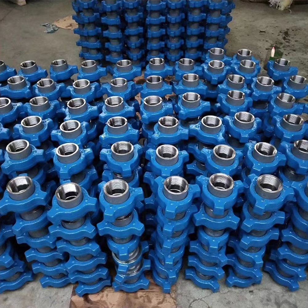
Quick Answer: What Is a Hammer Union?
A hammer union, also called a wing union or flow iron union in oilfield service, is a mechanical pressure connection that joins two flowline components without rotating the connected pipe. A complete union normally consists of a male sub, female sub, wing nut and figure-specific seal system. The wing nut engages a heavy-duty ACME thread and pulls the matched subs together to load the sealing interface.
Need Hammer Unions for an Existing Flow Iron System?
Send GPE the figure number, nominal size, working pressure, threaded or butt-weld end, service condition and quantity. If dimensional matching is required, include the existing drawing, part number or measured connection data.
How Does a Hammer Union Work?
A hammer union creates a pressure connection by drawing two matched subs together with a wing nut. Unlike a conventional threaded pipe joint, the connected pipe or equipment does not have to rotate during final makeup or breakout. This is one reason hammer unions are widely used in temporary and skid-mounted high-pressure flowlines.
The figure, size, bore, sealing geometry and service class must correspond to the intended connection.
The nut is started correctly so the threads engage without cross-threading or forcing.
As the wing nut advances, the male and female connection geometry moves into the designed pressure-sealing position.
Depending on the figure, sealing may use precision metal seating, an O-ring, a resilient seal ring or an engineered high-pressure seal system.
Figure, size, pressure marking, service class, nut engagement and physical condition should be confirmed before the line is placed in service.
Main Hammer Union Components
The four principal elements of a complete hammer union work together as one pressure-containing connection. Replacement parts should therefore be selected by figure, size, geometry, seal system and service condition rather than by appearance.
Male Sub
Forms one side of the connection and contains the male sealing nose, flow bore and external threaded or butt-weld interface.
Female Sub
Receives the male sub and contains the matching seat or seal groove plus the external ACME thread engaged by the wing nut.
Wing Nut
Draws the two subs together. Its external lugs provide the impact surfaces used during controlled makeup and breakout.
Seal System
Provides the figure-specific pressure barrier through metal seating, O-ring assistance, lip-type seals or engineered high-pressure seal designs.
Hammer Union Types and Figure Numbers
Hammer unions are commonly identified by a figure number. The figure is not a nominal size and it does not simply describe the outside appearance. It identifies a connection family with a defined pressure range, interface geometry and sealing arrangement.
| Figure | GPE Pressure Reference | Typical Seal / Interface | Typical Service Positioning |
|---|---|---|---|
| Fig 100 | 1,000 psi | Metal-to-metal seating | Compatible low-pressure water and oil lines |
| Fig 200 / 206 | 2,000 psi | Precision seat or O-ring-assisted seal | General service and manifold piping |
| Fig 400 | 4,000 psi | Ball-and-cone metal seal | Medium-pressure service |
| Fig 602 | 6,000 psi | Replaceable resilient seal ring | Cementing and circulation |
| Fig 1002 | 10,000 psi | Replaceable high-pressure seal | Cementing, acidizing and testing |
| Fig 1003 | Figure/size dependent | Misaligning ball-seat configuration | Controlled angular alignment |
| Fig 1502 | 15,000 psi | High-pressure replaceable seal ring | Hydraulic fracturing and high-pressure flow iron |
| Fig 2002 | 20,000 psi | Engineered ultra-high-pressure interface | Pressure pumping and testing |
| Fig 2202 | Approved sour-service configuration | Controlled-hardness materials and sour-service seals | H2S well-service lines |
For a deeper technical review of the principal high-pressure fracturing connection, see the Fig 1502 Hammer Union Dimensions, Pressure Rating & Specifications Guide.
Hammer Union Pressure Ratings: What Does the Figure Number Mean?
A common mistake is to treat the figure number as a direct pressure value or as a size code. For example, Fig 1502 does not mean 1,502 psi. In GPE’s published hammer union range, Fig 1502 is the principal 15,000 psi connection family for hydraulic fracturing and high-pressure flow iron.
Figure Number
Identifies the union family, pressure class, sealing concept and connection geometry.
Nominal Size
Identifies the connection size, such as 2 in or 3 in, but does not by itself define every bore or outside dimension.
Working Pressure
Must be confirmed for the exact figure and approved configuration. The complete system remains limited by its lowest-rated component.
Service Class
Standard, low-temperature and H2S configurations can require different materials, hardness control and seals.
What Sizes Do Hammer Unions Come In?
GPE’s published hammer union manufacturing range covers nominal sizes from 1 to 5 in. Availability depends on the selected figure, pressure class, end connection and service configuration.
Size alone is not enough for purchasing. A request such as “2-inch hammer union” leaves several critical details undefined.
Incomplete Request
“2-inch hammer union.”
This does not define figure, pressure, end connection, service class or dimensional compatibility.
Better Technical Request
“2-inch Fig 1502 hammer union, required for 15K frac iron, threaded or butt-weld end as specified, with project service and quantity stated.”
This gives the supplier enough information to begin connection review.
For replacement work, also provide the existing drawing, part number, permanent markings or controlled measurements. Different manufacturers may use product revisions or dimensional details that should be formally checked before substitution.
Threaded vs Butt-Weld Hammer Unions
GPE supplies complete hammer union assemblies with threaded and butt-weld end configurations. The hammer union interface provides the quick mechanical connection; the external sub end determines how the union attaches to the adjoining pipe, valve or equipment.
| Selection Item | Threaded Hammer Union | Butt-Weld Hammer Union |
|---|---|---|
| External end | Approved thread form and orientation | Machined weld end matched to pipe geometry |
| Key data | Thread specification, nominal size, pin/box orientation where applicable | Pipe OD, bore, wall thickness, material and weld preparation |
| Typical purchasing focus | Thread compatibility and gauge confirmation | Pipe compatibility and fabrication drawing |
| Replacement check | Figure + size + thread + seal + service class | Figure + size + pipe geometry + seal + service class |
A description such as “Fig 1502 butt weld” is still incomplete if pipe OD, bore, wall thickness, material and weld preparation have not been specified.
Hammer Union Fittings and Connection Configurations
The phrase hammer union fittings is often used broadly for union-end flow iron components and the connection hardware used around them. In a complete pressure-pumping line, hammer union interfaces can be found on rigid pipe, integral fittings, swivel joints, plug valves, check valves and manifold branches.
Complete Union
Matched male sub, female sub, wing nut and figure-specific sealing components supplied as one connection assembly.
Male / Female Components
Individual subs used in approved equipment fabrication, repair or replacement when the complete interface has been verified.
Blind Components
Male or female blind unions, caps and plugs used in approved test, isolation and transport arrangements.
Union-End Pup Joints
Rigid straight flow iron sections with male/male, male/female or female/female hammer union ends.
Integral Fittings
Elbows, tees, crosses, reducers and multi-port blocks using approved hammer union end combinations.
Valve & Swivel Connections
High-pressure plug valves, check valves and swivel joints can be configured with compatible hammer union interfaces.
Hammer Union vs Wing Union: Are They the Same?
In oilfield flowline terminology, wing union is commonly used as an alternative name for a hammer union. The name refers to the external lugs or “wings” on the union nut that provide controlled impact surfaces during makeup and breakout.
For procurement, however, “wing union” is not a complete specification. The buyer should still provide the figure number, nominal size, working pressure, end connection and service class.
Where Are Hammer Unions Used?
Hammer unions are used where pressure-containing flowline equipment must be assembled, removed or serviced efficiently. GPE supplies them for fracturing, cementing, acidizing, testing, pressure pumping and flowback systems.
Hydraulic Fracturing
Connections between frac pumps, discharge piping, plug valves, check valves, swivel joints, manifolds and wellhead-side flow iron.
Cementing
Connections on cementing units, pump lines, manifolds, cement heads, circulation heads and flush lines.
Acidizing
High-pressure treatment lines where connection materials and seals must match the fluid chemistry and service requirement.
Well Testing
Temporary pressure lines and test assemblies requiring fast rig-up and controlled connection identification.
Flowback
Pressure-containing lines requiring planned bore, erosion, wall-thickness, seal and connection inspection.
Equipment Integration
Pup joints, rigid pipe, integral fittings, manifolds and packaged pressure-control equipment using union-end interfaces.
How Hammer Unions Fit Into a Frac Iron System
A hammer union is not an isolated product. Its value comes from creating controlled, serviceable connections between pressure-pumping components throughout the high-pressure flow path.
The actual flow path depends on the pumping spread and project design. Every connection in the system must be checked for figure, pressure class, bore, geometry and service compatibility.
Building or Replacing a High-Pressure Flowline?
GPE can review the hammer union together with the connected pup joint, valve, swivel or manifold interface so the figure, bore, end connection and service requirement are checked as one system.
How to Select the Right Hammer Union
The most reliable selection sequence starts with the system requirement rather than the appearance of the existing union.
Provide both normal and maximum system pressure and identify the lowest-rated connected component.
Use the equipment drawing, permanent marking or approved system specification to confirm the required figure.
The connection should match the adjoining flow iron and should not create an unintended restriction.
Specify threaded or butt weld and provide the required thread or pipe geometry.
State fracturing fluid, cement, acid, test fluid, flowback medium and proppant information where applicable.
Confirm Standard, Low-Temperature or H2S service requirements and the expected operating temperature range.
State whether you need a complete union, male sub, female sub, wing nut, seal, blind component or repair kit.
Include drawings, part numbers, permanent markings, measured dimensions or physical sample data.
State material-certificate, NDE, hardness, dimensional, pressure-test, traceability and documentation requirements.
This allows the quotation to address manufacturing scope, packaging and export delivery planning.
Hammer Union Selection Example
A structured inquiry is easier to review than a generic request for “high-pressure hammer unions.” The example below shows the type of information that helps define the connection.
| Requirement | Example Information |
|---|---|
| Application | Hydraulic fracturing flow iron |
| Figure | Fig 1502 |
| Working pressure | 15,000 psi system requirement |
| Nominal size | 2 in |
| End configuration | Threaded or butt weld as defined by the adjoining equipment |
| Service fluid | Frac fluid / proppant-bearing slurry |
| Service class | Project-defined Standard, Low-Temperature or H2S configuration |
| Required scope | Complete assembly plus spare seal package |
| Documentation | Project-specific material, inspection, test and traceability documents |
| Quantity | State required sets and spare-part quantities |
Hammer Union Inspection Before Use
Inspection should focus on the features that control identification, mechanical engagement and pressure sealing. The exact inspection scope depends on service history, owner procedure and project requirements.
- Confirm permanent figure marking.
- Confirm nominal size and working pressure marking.
- Confirm Standard, Low-Temperature or H2S service identification.
- Inspect wing nut lugs for severe wear, flattening, mushrooming or cracking.
- Inspect ACME threads for cross-threading, deformation, corrosion and excessive wear.
- Inspect male and female sealing surfaces.
- Inspect the seal ring, O-ring or figure-specific sealing element.
- Check bore condition for erosion, corrosion or mechanical damage.
- Confirm that the connected figure and size are matched.
- Verify that the line is fully depressurized before any makeup, breakout or disassembly.
Manufacturing, Inspection and Testing at GPE
GPE manufactures hammer unions from forged carbon or alloy steel according to the approved figure, service requirement and drawing. Manufacturing control covers material identification, forging, heat treatment, CNC machining, connection inspection, marking and figure-specific hydrostatic pressure testing.
Material & Traceability
Material certificates, heat-number identification and controlled material selection are applied according to the specified figure and service.
Machining
Bores, sealing seats, grooves, ACME threads and external threaded or butt-weld ends are CNC machined to the approved drawing.
Inspection
Specified material, UT, MPI, hardness, dimensional, thread, seal and visual inspection are performed according to the manufacturing and project plan.
Pressure Testing
The completed connection receives figure-specific hydrostatic pressure testing according to the approved product requirement.
Information to Send When Requesting Hammer Unions
For faster technical review and quotation, send the connection and service information together rather than requesting only by product name.
- Figure number
- Nominal size
- Normal working pressure
- Maximum working pressure
- Required flow bore
- Threaded or butt-weld construction
- Thread type and orientation
- Pipe OD, bore, wall thickness and weld preparation
- Male, female, blind or complete assembly
- Service fluid
- Proppant or solids information
- Operating temperature
- Standard, Low-Temperature or H2S service
- Existing drawing, part number or sample data
- Inspection and testing requirements
- Documentation and traceability requirements
- Quantity
- Destination and requested delivery date
Request a High-Pressure Hammer Union Proposal
GPE supplies complete hammer unions, male and female subs, wing nuts, seals, blind components and repair parts for fracturing, cementing, acidizing, testing, pressure-pumping and flowback systems. Send your figure, size, pressure, end connection and service requirements for engineering review.