

Description
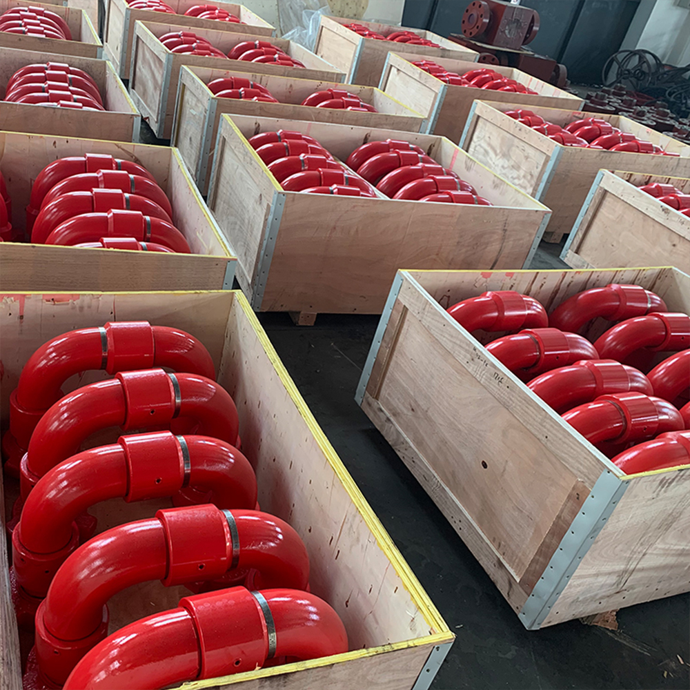
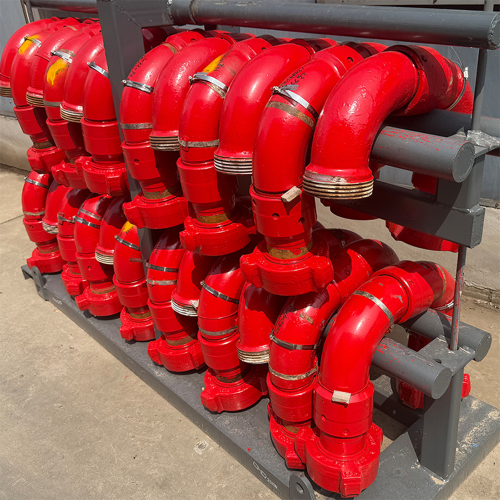
GPE manufactures High-Pressure Swivel Joints for hydraulic fracturing, cementing, acidizing, well testing, choke-and-kill lines, circulation systems and abrasive flowback service.
Each swivel joint consists of forged alloy-steel pressure bodies, precision-machined ball-bearing races, a pressure-supported sealing assembly and high-pressure union ends. Every swivel section rotates through 360 degrees, allowing rigid Flow Iron components to be aligned without applying excessive bending loads to Plug Valves, Pup Joints, Check Valves, manifold inlets or wellhead connections.
The GPE product range covers:
- Nominal sizes from 1 to 4 in
- Working pressures from 6,000 to 20,000 psi
- Style 10, 20, 30, 50, 60, 80 and 100
- Long-Sweep and Short-Sweep designs
- Standard Service and H₂S Service
- Fig 602, Fig 1002, Fig 1502, Fig 2002 and Fig 2202 connections
- Male × Male, Male × Female and Female × Female ends
- Complete seal, bearing and redress kits
- Engineered replacement configurations for existing Flow Iron systems
Product Short Description
GPE High-Pressure Swivel Joints provide flexible, pressure-retaining connections between rigid high-pressure flowline components.
The forged alloy-steel construction withstands pressure pulsation, pipeline vibration, mechanical impact and repeated rig-up operations. The smooth internal bore limits abrupt flow-area changes, reduces pressure loss and controls erosion concentration when transporting cement slurry, acid, drilling fluid, completion fluid and proppant-laden fracturing fluid.
The sealing assembly uses a primary pressure seal, a metallic anti-extrusion support ring, a secondary environmental seal and a pressure-relief port. This structure protects the ball-bearing chamber, controls seal extrusion and provides a visible indication of primary seal wear.
Product Highlights
- 1–4 in nominal size range
- 6,000–20,000 psi working-pressure range
- 42–140 MPa pressure classes
- Style 10, 20, 30, 50, 60, 80 and 100
- Long-Sweep and Short-Sweep configurations
- 360-degree rotation at each swivel section
- One-, two-, three- and multi-plane articulation
- Forged alloy-steel pressure bodies
- Controlled quenching and tempering
- CNC-machined flow bores and sealing surfaces
- Precision ball-bearing race structure
- Smooth internal flow path
- Low local flow resistance
- Reduced turbulence at bore transitions
- High resistance to pressure pulsation
- High resistance to mechanical vibration
- Pressure-supported primary seal
- Metallic anti-extrusion backup ring
- Secondary environmental seal
- Pressure-relief and leak-indication port
- Grease-lubricated bearing races
- Standard and H₂S Service construction
- PU temperature class
- Fig 602, 1002, 1502, 2002 and 2202 ends
- Male and female end combinations
- Material heat-number traceability
- Individual serial-number marking
- Forging ultrasonic inspection
- Magnetic-particle inspection
- Hardness inspection
- Hydrostatic pressure testing
- Seal-integrity testing
- Rotational-function testing
- Complete spare-parts packages
Main Technical Specifications
| Parameter | GPE Manufacturing Range |
|---|---|
| Product | High-Pressure Swivel Joint |
| Product category | High-Pressure Flow Iron |
| Nominal sizes | 1, 1-1/2, 2, 3 and 4 in |
| Working pressure | 6,000–20,000 psi |
| Metric pressure class | 42–140 MPa |
| Pressure series | 6K, 10K, 15K and 20K |
| Working temperature | -29°C to 121°C |
| Temperature class | PU |
| Service environment | Standard Service or H₂S Service |
| Swivel styles | Style 10, 20, 30, 50, 60, 80 and 100 |
| Bend geometry | Long Sweep or Short Sweep |
| Rotation | 360° at each swivel section |
| Body construction | Forged alloy steel |
| Manufacturing process | Forging, heat treatment and CNC machining |
| Bearing structure | Precision ball-bearing races |
| Primary seal | Pressure-supported packing |
| Seal support | Metallic anti-extrusion ring |
| Secondary seal | Environmental protection seal |
| Pressure indication | Pressure-relief and leak-detection port |
| Internal flow path | Smooth, uniform bore |
| End connections | Fig 602, 1002, 1502, 2002 and 2202 |
| End combinations | M × M, M × F and F × F |
| Main applications | Fracturing, cementing, acidizing, testing, circulation and flowback |
| Choke-and-kill service | API Spec 16C |
| H₂S material selection | NACE MR0175 / ISO 15156 |
| Inspection | UT, MPI, hardness, dimensional and functional inspection |
| Pressure testing | Hydrostatic body and seal-integrity testing |
| Supply scope | Complete joint, seal kit, bearing kit and redress parts |
Pressure and Connection Classes
| Working Pressure | Metric Class | Connection Family | Service Positioning |
|---|---|---|---|
| 6,000 psi | 42 MPa | Fig 602 | Cementing, circulation and medium-pressure service |
| 10,000 psi | 70 MPa | Fig 1002 | Cementing, acidizing, well testing and high-pressure service |
| 15,000 psi | 105 MPa | Fig 1502 | Hydraulic fracturing and high-pressure Flow Iron |
| 20,000 psi | 140 MPa | Fig 2002 | Ultra-high-pressure pumping and test lines |
| 15,000 psi | 105 MPa | Fig 2202 | H₂S and sour-gas service |
Each component is permanently marked with:
- Nominal size
- Connection figure
- Working pressure
- Service class
- Temperature class
- Serial number
- Heat number
- Manufacturing date
The complete assembly pressure rating equals the rating of its lowest-rated component.
Standard Size and Pressure Matrix
| Nominal Size | 6K | 10K | 15K | 20K |
|---|---|---|---|---|
| 1 in | ● | ● | Engineered configuration | Engineered configuration |
| 1-1/2 in | ● | ● | Engineered configuration | Engineered configuration |
| 2 in | ● | ● | ● | ● |
| 3 in | ● | ● | ● | ● |
| 4 in | ● | ● | ● | Engineered configuration |
The approved manufacturing drawing defines:
- Minimum flow bore
- Overall dimensions
- Bend radius
- Union-end geometry
- Wall thickness
- Ball-race dimensions
- Seal-groove dimensions
- Product weight
Swivel Joint Style Guide
Style 10 Swivel Joint
Style 10 consists of three swivel sections and two elbows.
It provides three-plane articulation and a U-shaped flow path for connecting offset high-pressure flowlines.
Style 10 is used in:
- Frac Pump discharge lines
- Steel hose loops
- Cementing lines
- Pump-to-manifold connections
- Temporary high-pressure piping
- Flowlines exposed to movement and vibration
GPE manufactures Style 10 with:
- Male × Male ends
- Male × Female ends
- Female × Female ends
- Long-Sweep elbows
- Short-Sweep elbows
- Standard Service construction
- H₂S Service construction
Style 20 Swivel Joint
Style 20 is a single straight-through swivel coupling.
It provides one-plane rotation without changing the primary flow direction.
Style 20 is used for:
- Inline rotational alignment
- Compact manifold connections
- Rigid piping assembly
- Equipment connections with limited installation space
- Individual swivel positions inside complex assemblies
Style 30 Swivel Joint
Style 30 consists of one swivel section and one angled elbow.
It provides one rotational plane and one fixed change in flow direction.
Style 30 is used for:
- Compact flowline offsets
- Pump discharge routing
- Test-line connections
- Manifold inlet alignment
- Skid-mounted high-pressure piping
Style 50 Swivel Joint
Style 50 consists of two swivel sections and two elbows.
It provides two-plane articulation with a compact U-shaped geometry.
Style 50 is one of the principal configurations for:
- Hydraulic fracturing lines
- Cementing-unit discharge lines
- Frac Pump manifold connections
- Steel hose loops
- Plug Valve connections
- Wellhead and Frac Tree rig-up
Style 60 Swivel Joint
Style 60 consists of two swivel sections and one elbow.
It provides two-plane articulation in a compact 90-degree configuration.
Style 60 is used for:
- Restricted rig-up areas
- Compact equipment skids
- Vertical-to-horizontal flowline transitions
- Pump and manifold connections
- Test and circulation systems
Style 80 Swivel Joint
Style 80 consists of three swivel sections and three elbows.
It provides three-plane articulation and an offset flow path for complex high-pressure piping layouts.
Style 80 is used for:
- Uneven wellsite layouts
- Equipment with different elevations
- High-pressure flowlines exposed to movement
- Pump-to-manifold connections
- Temporary treatment-iron systems
- Multi-direction routing around fixed equipment
Style 100 Swivel Joint
Style 100 is an extended-leg U-bend swivel assembly.
The extended geometry provides increased routing dimensions for installations that require larger offsets between connected equipment.
Style 100 is supplied in:
- Male × Male configuration
- Male × Female configuration
- Standard Service
- H₂S Service
- Long-Sweep construction
Long-Sweep Swivel Joint
The Long-Sweep design uses a larger bend radius and a gradual internal flow transition.
This geometry:
- Reduces abrupt directional change
- Reduces local turbulence
- Reduces pressure loss
- Reduces particle impact at the outer bend
- Distributes erosion over a larger internal surface
- Extends inspection intervals in abrasive service
- Improves high-rate pumping efficiency
Long-Sweep Swivel Joints are used for:
- Proppant-laden fracturing fluid
- High-rate cement slurry
- Abrasive flowback
- Acidizing systems
- Extended pumping operations
- High-flow treatment lines
Short-Sweep Swivel Joint
The Short-Sweep design uses a compact bend radius.
This construction:
- Reduces the installation envelope
- Reduces assembly height
- Simplifies skid integration
- Fits restricted rig-up areas
- Reduces total assembly length
- Supports compact high-pressure piping layouts
Short-Sweep Swivel Joints are used where installation space controls the flowline geometry.
Working Principle
Each swivel section consists of:
- Male swivel sub
- Female swivel body
- Ball-bearing race
- Bearing balls
- Primary pressure seal
- Metallic anti-extrusion ring
- Secondary environmental seal
- Grease-retention structure
- Pressure-relief port
- Mechanical retaining components
The ball-bearing races maintain axial engagement between the male and female swivel sections while permitting 360-degree rotation.
The primary seal contains process pressure. The metallic support ring prevents pressure-driven seal extrusion. The secondary seal prevents sand, water, cement and atmospheric contamination from entering the bearing chamber.
The pressure-relief port releases trapped pressure from the bearing cavity and provides visual indication of primary seal leakage.
The joint provides articulation for rig-up, alignment and controlled line movement. It is not used as a high-speed continuous rotary coupling.
Rig-up, disassembly and deliberate repositioning are performed after the flowline is fully depressurized.
Smooth-Bore Flow Path
The internal flow path maintains a uniform bore through:
- Swivel bodies
- Elbows
- Union ends
- Seal transitions
The smooth bore provides:
- Reduced pressure loss
- Reduced flow separation
- Reduced turbulence
- Lower local fluid velocity peaks
- Reduced erosion concentration
- Improved solids transport
- Easier internal cleaning
- More predictable hydraulic performance
The bore diameter is machined according to the pressure class, connection figure and approved drawing.
Sealing Structure
Primary Pressure Seal
The primary seal forms the pressure barrier between rotating metal components.
It withstands:
- High internal pressure
- Pressure cycling
- Mechanical vibration
- Repeated articulation
- Temperature change
- Abrasive fluid exposure
Metallic Anti-Extrusion Ring
The metallic support ring controls the clearance behind the primary seal.
It prevents the seal from being forced into the metal gap under high differential pressure.
This structure:
- Protects the sealing element
- Maintains seal geometry
- Improves pressure-cycle stability
- Reduces extrusion damage
- Extends redress intervals
Secondary Environmental Seal
The secondary seal protects the ball-bearing chamber from:
- Frac sand
- Cement
- Drilling fluid
- Water
- Dust
- Atmospheric contamination
It also retains lubricant inside the bearing races.
Pressure-Relief Port
The pressure-relief port prevents pressure accumulation inside the bearing chamber.
Fluid discharge from this port identifies primary seal wear and triggers immediate isolation, depressurization and redressing.
Ball-Bearing System
Precision-machined ball-bearing races transfer:
- Axial load
- Radial load
- Piping reaction
- Mechanical vibration
- Rig-up movement
The bearing structure maintains alignment between the male and female swivel sections and ensures smooth rotation during installation.
Bearing-race surfaces receive controlled hardening to improve:
- Wear resistance
- Contact-fatigue resistance
- Surface strength
- Dimensional stability
- Service life
Forged Alloy-Steel Construction
GPE manufactures the pressure-containing bodies from high-strength alloy-steel forgings.
The manufacturing sequence includes:
- Raw-material verification
- Heat-number identification
- Forging
- Preliminary ultrasonic inspection
- Rough machining
- Quenching and tempering
- Mechanical-property testing
- CNC machining
- Flow-bore machining
- Bearing-race machining
- Seal-groove machining
- Union-end machining
- Surface NDE
- Component assembly
- Pressure testing
- Final marking and inspection
Forged construction provides:
- Uniform material properties
- High pressure strength
- High impact resistance
- High fatigue resistance
- Stable heat-treatment response
- Reliable bearing-race support
- Consistent wall thickness
Standard Service
Standard-Service Swivel Joints handle:
- Fracturing fluid
- Cement slurry
- Drilling fluid
- Completion brine
- Water
- Oil-based service fluid
- Well-test fluid
- Compatible flowback fluid
Standard-Service components remain separated from H₂S Service components throughout manufacturing, assembly, marking and storage.
H₂S and Sour Service
GPE H₂S Service Swivel Joints use:
- Controlled-hardness alloy-steel bodies
- Qualified heat-treatment procedures
- H₂S-compatible sealing materials
- Sour-service bearing and retaining components
- Full material traceability
- Hardness inspection
- NACE-compliant material selection
The purchase specification defines:
- H₂S partial pressure
- CO₂ content
- Chloride concentration
- Fluid pH
- Maximum operating temperature
- Total system pressure
- Acid concentration
NACE MR0175 / ISO 15156 controls metallic-material selection for H₂S-containing oil and gas production environments; it supplements the governing product design and manufacturing requirements.
Hydraulic Fracturing Applications
GPE Swivel Joints connect:
- Frac Pumps
- Fluid End discharge lines
- Pump Discharge Manifolds
- Check Valves
- Plug Valves
- Straight Pipe Assemblies
- Frac Missiles
- Zipper Manifolds
- Frac Trees
For high-rate proppant service, the product uses:
- Long-Sweep geometry
- Smooth internal bore
- Forged pressure bodies
- Pressure-supported seals
- Metallic anti-extrusion rings
- Defined UT inspection locations
- Replaceable seal and bearing kits
Industry-standard Fig 1502 Flow Iron Swivels are widely used in hydraulic fracturing, cementing, well testing and abrasive flowback service.
Cementing Applications
The swivel joint connects:
- Cementing Units
- Cementing Manifolds
- High-Pressure Pumps
- Plug Valves
- Cement Heads
- Circulating Heads
- Wellhead equipment
The smooth bore reduces cement accumulation and simplifies flushing after cement placement.
Acidizing Applications
Acidizing versions use materials and sealing elements selected for:
- Acid concentration
- Corrosion inhibitor
- Operating temperature
- H₂S exposure
- CO₂ exposure
- Chloride content
The flowline is flushed and neutralized immediately after service.
Well Testing and Flowback
Well-testing and flowback fluids contain:
- Formation sand
- Residual proppant
- Scale
- Completion debris
- Water
- Hydrocarbon liquid
- Gas
- Corrosive contaminants
Flowback Swivel Joints receive scheduled:
- Wall-thickness inspection
- Bend inspection
- Seal inspection
- Bearing-clearance inspection
- Union-end inspection
- Hydrostatic recertification
Choke-and-Kill Service
GPE manufactures swivel unions for choke-and-kill systems in accordance with API Spec 16C.
API Spec 16C covers swivel unions used in choke-and-kill equipment and defines requirements for design, materials, quality control, inspection, testing, marking, storage and shipment. The current specification is API Spec 16C, Third Edition, with subsequent addenda and errata.
Fracturing, cementing, acidizing and flowback Swivel Joints are manufactured under:
- Approved GPE engineering drawings
- Rated pressure class
- Material specifications
- Customer purchase specifications
- Inspection and Test Plan
- Hydrostatic-test procedure
Manufacturing Quality Control
GPE quality control includes:
- Raw-material certificate review
- Chemical-composition verification
- Heat-number traceability
- Heat-treatment monitoring
- Tensile-property testing
- Yield-strength testing
- Elongation testing
- Impact testing for low-temperature orders
- Body hardness inspection
- H₂S hardness inspection
- Forging ultrasonic inspection
- Magnetic-particle inspection
- Flow-bore dimensional inspection
- Wall-thickness inspection
- Bearing-race inspection
- Seal-groove inspection
- Union-end dimensional inspection
- Assembly-clearance inspection
- Rotation inspection
- Hydrostatic body testing
- Seal-integrity testing
- Final visual inspection
Pressure Testing
Every GPE Swivel Joint receives:
- Body hydrostatic testing
- Primary seal testing
- Pressure-hold testing
- Visual leakage inspection
- Pressure-relief-port inspection
- Post-test rotational inspection
The approved Inspection and Test Plan defines:
- Test medium
- Test pressure
- Pressure ramp
- Stabilization time
- Hold time
- Acceptance criteria
- Recording method
API Spec 16C requires hydrostatic body testing of each swivel union before final acceptance for products within its scope.
Product Documentation
The order documentation includes:
- Certificate of Conformity
- Product datasheet
- General arrangement drawing
- Dimensional drawing
- Material Test Certificate
- Heat-treatment record
- Mechanical-property report
- Hardness report
- Ultrasonic-inspection report
- Magnetic-particle-inspection report
- Dimensional-inspection report
- Wall-thickness report
- Hydrostatic-test report
- Pressure-test chart
- Seal-integrity-test report
- Serial-number traceability list
- Operating and maintenance manual
- Redress instructions
- Spare-parts list
- Packing list
Maintenance and Redressing
Routine maintenance includes:
- External cleaning
- Leak-port inspection
- Grease-port inspection
- Bearing lubrication
- Rotation inspection
- Axial-clearance inspection
- Radial-clearance inspection
- Union-thread inspection
- Seal-surface inspection
- Wall-thickness measurement
- Outer-bend inspection
- Seal replacement
- Bearing replacement
- Hydrostatic recertification
GPE supplies:
- Primary packing
- Metallic backup rings
- Secondary seals
- Bearing balls
- Grease retainers
- Retaining rings
- Grease fittings
- Seal kits
- Bearing kits
- Complete redress kits
Common Failure Modes
Leakage at the Swivel Section
Primary causes:
- Worn pressure packing
- Damaged metallic backup ring
- Scratched sealing surface
- Excessive bearing clearance
- Incorrect assembly
- Abrasive contamination
Corrective action:
- Isolate and depressurize the line
- Disassemble the swivel section
- Inspect sealing surfaces
- Replace the complete seal kit
- Measure bearing clearance
- Pressure-test before returning to service
Leakage from the Pressure-Relief Port
This condition identifies primary seal failure.
The joint is removed from service immediately and receives complete redressing and pressure testing.
Difficult Rotation
Primary causes:
- Insufficient lubrication
- Corroded bearing balls
- Packed cement or sand
- Damaged bearing races
- Excessive external piping load
- Misaligned Flow Iron
Corrective action:
- Depressurize the assembly
- Clean the joint
- Inspect bearing races
- Replace damaged bearing components
- Correct the rig-up alignment
Rapid Bend Erosion
Primary causes:
- High proppant concentration
- Excessive flow velocity
- Short-Sweep geometry
- Extended pumping duration
- Abrupt flow transitions
- Fixed bend orientation
Corrective action:
- Use Long-Sweep construction
- Establish scheduled UT inspection
- Record pumped volume and proppant mass
- Remove the joint at the minimum wall-thickness limit
Frequently Asked Questions
What sizes does GPE manufacture?
GPE manufactures 1, 1-1/2, 2, 3 and 4 in High-Pressure Swivel Joints.
What working pressures are supplied?
The pressure series includes:
- 6,000 psi
- 10,000 psi
- 15,000 psi
- 20,000 psi
What Swivel Joint styles are supplied?
GPE manufactures:
- Style 10
- Style 20
- Style 30
- Style 50
- Style 60
- Style 80
- Style 100
Industry naming defines Style 10 as three swivels with two elbows, Style 20 as a single swivel coupling, Style 30 as a single swivel with one elbow, Style 50 as two swivels with two elbows, Style 60 as two swivels with one elbow and Style 80 as three swivels with three elbows.
What is the difference between Style 10 and Style 50?
Style 10 provides three-plane articulation through three swivel sections and two elbows.
Style 50 provides two-plane articulation through two swivel sections and two elbows.
What is Style 100?
Style 100 is an extended-leg U-bend swivel assembly used for complex routing and larger dimensional offsets.
What is the difference between Long Sweep and Short Sweep?
Long Sweep uses a larger bend radius to reduce pressure loss, turbulence and erosion concentration.
Short Sweep uses a compact bend radius to reduce installation space.
Which connection is used for 15,000 psi fracturing?
Fig 1502 is used for 15,000 psi Standard-Service fracturing Flow Iron.
Which connection is used for 20,000 psi service?
Fig 2002 is used for 20,000 psi Standard Service.
Which connection is used for 15,000 psi H₂S Service?
Fig 2202 is used for 15,000 psi Sour Service.
Does the joint rotate through 360 degrees?
Yes. Each swivel section provides full 360-degree rotational positioning.
Is it a continuous rotary union?
No. The product provides articulation and alignment for high-pressure Flow Iron. It is not a high-speed continuous rotary coupling.
Does GPE supply replacement-compatible Swivel Joints?
Yes. GPE manufactures replacement configurations from approved drawings, connection dimensions, product samples and existing equipment data.
Does GPE supply seal kits?
Yes. GPE supplies complete seal, bearing and redress kits for every manufactured model.
Is API Spec 16C used for every Swivel Joint?
API Spec 16C governs Swivel Unions supplied for choke-and-kill equipment.
Fracturing, cementing, acidizing, testing and flowback products follow GPE engineering drawings, rated pressure requirements and customer purchase specifications.
Information Required for Quotation
Provide:
- Nominal size
- Working pressure
- Style number
- Long Sweep or Short Sweep
- Connection figure
- Male or female end configuration
- Required flow bore
- Standard or H₂S Service
- Minimum operating temperature
- Maximum operating temperature
- Service fluid
- Maximum flow rate
- Maximum proppant concentration
- Proppant type
- Maximum particle size
- Acid concentration
- H₂S partial pressure
- CO₂ concentration
- Chloride concentration
- Fluid pH
- Overall dimensional limits
- Center-to-end dimensions
- Existing part number
- Existing equipment drawing
- Required material documentation
- NDE requirements
- Hydrostatic-test requirements
- Third-party inspection
- Spare-kit quantity
- Product quantity
- Destination country
- Delivery schedule
Request a Technical Quotation
GPE manufactures complete High-Pressure Swivel Joint systems for fracturing, cementing, acidizing, well testing, circulation, choke-and-kill and flowback operations.
Our manufacturing range includes:
- 1–4 in sizes
- 6,000–20,000 psi pressure ratings
- Style 10, 20, 30, 50, 60, 80 and 100
- Long-Sweep and Short-Sweep designs
- Fig 602, 1002, 1502, 2002 and 2202 ends
- Male × Male, Male × Female and Female × Female configurations
- Standard and H₂S Service
- Replacement-compatible dimensions
- Complete material and pressure-test documentation
- Seal, bearing and redress kits
Send the required size, pressure rating, Style, connection, service environment, temperature, dimensions and quantity to receive the correct technical proposal.
Email: info@gpepump.com
Reviews
There are no reviews yet.