

Description
Product Overview
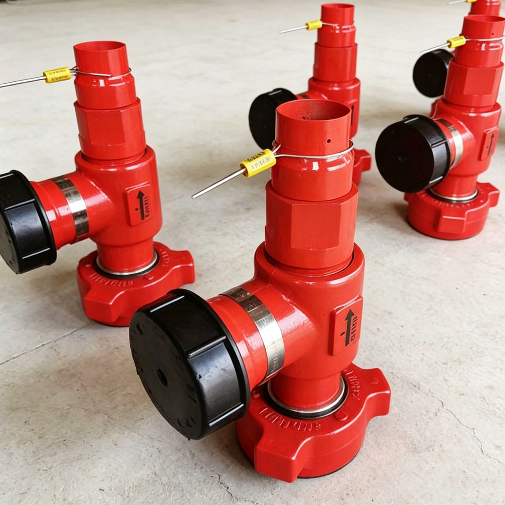
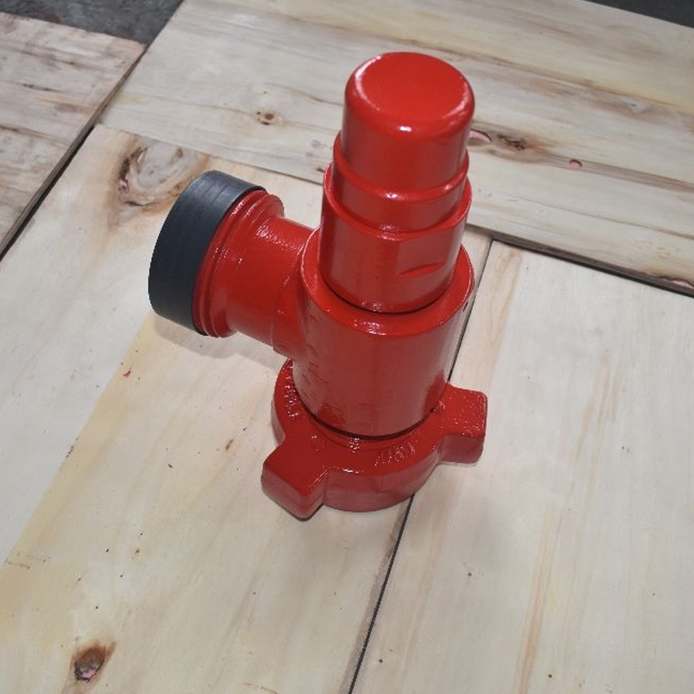
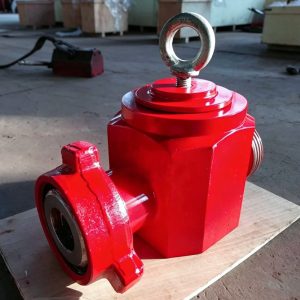
GPE manufactures direct-acting, self-resetting Emergency Relief Valves for reciprocating plunger pumps, hydraulic fracturing systems, cementing units, high-pressure manifolds, pressure-control lines and liquid-service Flow Iron.
The valve uses a spring-loaded metal ball and seat structure. A calibrated disc-spring stack applies closing force to the ball through the internal keeper. When inlet pressure rises above the preset relief pressure, hydraulic force lifts the ball from the seat and opens the discharge path. After inlet pressure falls below the spring closing force, the ball automatically reseats and restores the pressure barrier.
A top-mounted adjustment screw changes the spring preload and sets the opening pressure. The setting is secured with a locking and sealing structure after calibration. GPE supplies set-pressure configurations from 5,000 to 20,000 psi within the approved valve-body, spring-package and connection rating.
The standard product is a 2 in high-pressure liquid-service valve with male × female Flow Iron connections. It is manufactured for Standard Service, Low-Temperature Service and H₂S Service, with project-specific pressure settings, end connections, spring packages and repair kits.
This valve provides automatic protection against short-duration overpressure events. It is not a pressure regulator, a continuous bypass valve, a choke valve or a substitute for correct pressure-relief system sizing.
Need an Emergency Relief Valve for Your Pump or Manifold?
GPE sets each Emergency Relief Valve according to the protected equipment, maximum allowable pressure, normal operating pressure, required relief setting, service fluid and end connection.
Send us your plunger-pump model, manifold pressure rating, required set pressure, connection and operating temperature. Our engineering team will prepare the matching valve configuration and factory quotation.
Request an Emergency Relief Valve Quote:
https://gpepump.com/contact/
Send Your Pressure and Connection Details:
info@gpepump.com
Product Short Description
GPE Emergency Relief Valves provide direct-acting and self-resetting overpressure protection for high-pressure liquid pumping systems.
The compact forged alloy-steel body contains a calibrated spring stack, keeper, wear-resistant metal ball, replaceable seat and high-pressure sealing components. The valve remains closed during normal operation. When inlet pressure exceeds the calibrated setting, the ball lifts and releases fluid through the outlet. The valve automatically closes after system pressure returns below the reseating pressure.
The adjustable set-pressure range covers 35–140 MPa / 5,000–20,000 psi. Standard 2 in configurations are used on Frac Pumps, triplex and quintuplex plunger pumps, cementing units, high-pressure Flow Iron, test lines and manifold systems.
Product Highlights
- Direct-acting pressure-relief operation
- Automatic opening at the calibrated set pressure
- Automatic reseating after the overpressure event
- 2 in nominal connection size
- Adjustable set pressure from 5,000 to 20,000 psi
- Metric setting range from 35 to 140 MPa
- 15K and 20K pressure-body configurations
- Compact vertical body structure
- Spring-loaded metal ball and seat
- Calibrated disc-spring stack
- Top-mounted pressure-adjustment screw
- Locking and tamper-control structure
- Replaceable ball, seat, seals and spring components
- Forged alloy-steel pressure body
- Controlled heat treatment
- CNC-machined seat and pressure surfaces
- Rapid response to liquid-pressure increase
- Stable mechanical resetting
- Male × Female high-pressure Flow Iron connections
- Fig 1502 configuration for 15K systems
- Engineered high-pressure union connections for 20K systems
- Standard Service
- Low-Temperature Service
- H₂S and Sour Service
- PU temperature class from -29°C to 121°C
- NACE MR0175 / ISO 15156 material selection
- Calibrated hydraulic set-pressure testing
- Hydrostatic body testing
- Opening-pressure verification
- Reseating inspection
- External leakage inspection
- Factory test certificate
- Complete spring, ball, seat and seal kits
- Replacement-compatible manufacturing
Main Technical Specifications
| Parameter | GPE Manufacturing Range |
|---|---|
| Product | Emergency Relief Valve |
| Alternative name | High-Pressure Safety Relief Valve |
| Valve type | Direct-acting, spring-loaded and self-resetting |
| Primary service | High-pressure liquid service |
| Nominal size | 2 in |
| Adjustable set pressure | 5,000–20,000 psi |
| Metric setting range | 35–140 MPa |
| Pressure-body classes | 15,000 and 20,000 psi |
| Standard working temperature | -29°C to 121°C |
| Temperature class | PU |
| Service environment | Standard, Low Temperature or H₂S Service |
| Closing element | Metal ball |
| Seat | Replaceable precision-machined metal seat |
| Spring system | Calibrated disc-spring stack |
| Pressure adjustment | Top-mounted threaded adjustment screw |
| Setting security | Locking and tamper-control structure |
| Reset method | Automatic mechanical reseating |
| Body construction | Forged and heat-treated alloy steel |
| Standard end arrangement | Male × Female |
| Connection options | Fig 1502 and engineered high-pressure Flow Iron connections |
| Installation position | Vertical installation with unrestricted discharge routing |
| Main applications | Plunger pumps, Frac Pumps, cementing units, manifolds and test lines |
| H₂S material selection | NACE MR0175 / ISO 15156 |
| Inspection | UT, MPI, hardness, dimensional and functional inspection |
| Pressure testing | Hydrostatic body, set-pressure, opening and reseating tests |
| Supply scope | Complete valve, calibrated spring package and redress kit |
Confirm the Correct Set Pressure and Connection
The relief setting must protect the lowest-rated component in the pump, manifold and Flow Iron system. The set pressure is selected above the maximum normal operating pressure and within the allowable pressure of the protected equipment.
Send GPE the maximum operating pressure, equipment MAWP, required set pressure, fluid, temperature, inlet connection, outlet routing and service class. We will select the correct pressure body, spring stack and connection configuration.
Confirm the Correct Relief Valve Configuration:
https://gpepump.com/contact/
Send Your Set-Pressure Requirements:
info@gpepump.com
Standard Pressure Configurations
| Required Set-Pressure Range | Metric Range | Valve Configuration |
| 5,000–10,000 psi | 35–70 MPa | 2 in calibrated liquid-service ERV |
| 10,000–15,000 psi | 70–105 MPa | 2 in 15K high-pressure ERV |
| 15,000–20,000 psi | 105–140 MPa | 2 in 20K engineered ERV |
The selected spring stack controls the adjustable set-pressure range. The valve body, seat throat, end connection and discharge system are matched to the required pressure class.
A 15,000 psi valve body does not authorize a relief setting above its rated pressure. The final nameplate states the body rating, calibrated set pressure, service class, temperature class and serial number.
Set Pressure vs Working Pressure
Set pressure and valve working pressure are different values.
Set Pressure
The set pressure is the calibrated inlet pressure at which the ball begins to lift from the seat and the valve starts relieving.
Valve Working Pressure
The valve working pressure is the maximum rated pressure of the complete pressure-containing assembly.
Protected Equipment MAWP
The maximum allowable working pressure of the pump, manifold or Flow Iron component is the highest pressure permitted for that equipment.
The relief valve is selected so that:
- Normal operating pressure remains below the set pressure
- Set pressure protects the lowest-rated system component
- Valve-body rating is equal to or higher than the maximum system pressure
- Discharge capacity matches the credible overpressure source
- Outlet backpressure remains within the approved system design
The valve setting is established from the complete pressure-system design, not from pump horsepower alone.
Direct-Acting Operating Principle
The valve operates through a direct balance between spring force and inlet hydraulic force.
Normal Operating Condition
During normal operation, the calibrated disc-spring stack pushes the keeper downward. The keeper applies closing force to the metal ball, holding it against the seat.
The valve remains closed while the hydraulic force acting on the ball remains below the calibrated spring force.
Overpressure Condition
When inlet pressure rises above the set pressure, the hydraulic force acting through the seat throat exceeds the spring force.
The ball lifts from the seat and opens the flow path from the high-pressure inlet to the discharge outlet.
The released liquid lowers pressure in the protected system.
Automatic Reseating
After inlet pressure falls below the spring closing force, the keeper pushes the ball back onto the seat.
The valve closes automatically and restores pressure containment.
The reseating pressure is lower than the initial opening pressure. This pressure difference prevents unstable rapid opening and closing around a single pressure point.
Disc-Spring Stack
The spring system uses a calibrated stack of disc springs to generate the required closing force in a compact vertical assembly.
The disc-spring structure provides:
- High force in a compact space
- Stable axial loading
- Controlled adjustment through the top screw
- Repeatable mechanical closure
- Replaceable spring packages
- Separate spring ranges for different pressure settings
Spring components are inspected for:
- Cracking
- Permanent deformation
- Corrosion
- Surface damage
- Incorrect stacking
- Loss of free height
- Heat damage
- Service-class mismatch
Spring components are installed according to the approved stacking sequence. Individual springs are not added, removed or reversed outside the controlled calibration procedure.
Ball and Seat Structure
The metal ball and replaceable seat form the primary pressure seal.
The ball and seat provide:
- Direct hydraulic opening
- Concentrated spring closing force
- Compact internal structure
- Rapid pressure response
- Replaceable high-wear components
- Controlled seat-throat area
- Stable pressure calibration
The ball and seat are inspected as a matched pressure-control interface.
Damage requiring replacement includes:
- Pitting
- Wire drawing
- Erosion
- Scoring
- Embedded solids
- Corrosion
- Seat-edge deformation
- Loss of sealing contact
The ball and seat are not repaired by uncontrolled grinding or field reshaping.
Pressure-Adjustment System
The top adjustment screw changes the compression of the disc-spring stack.
Turning the adjustment screw increases or decreases the spring preload and changes the opening pressure.
The complete setting process includes:
- Installing the correct spring package
- Mounting the valve on a calibrated liquid-pressure test bench
- Removing all trapped air from the test system
- Raising pressure gradually
- Adjusting spring preload
- Verifying opening pressure
- Verifying reseating
- Repeating the test for stability
- Locking the adjustment
- Applying the setting seal and identification
The set pressure is not adjusted while the valve is connected to a pressurized field system.
Self-Resetting Protection
The valve automatically returns to the closed position after the inlet pressure drops below the spring closing force.
This provides protection against:
- Short pump-pressure spikes
- Temporary blocked-flow conditions
- Rapid line-pressure rise
- Control-valve malfunction
- Pump discharge overpressure
- Pressure transients during switching
- Accidental isolation of a pressurized section
Automatic resetting avoids replacement of a shear element after every relief event.
The valve is still inspected after an overpressure event because the ball, seat, spring stack and discharge path have been exposed to abnormal pressure and flow.
Emergency Relief Valve vs Shear-Pin Relief Valve
| Spring-Loaded Emergency Relief Valve | Shear-Pin Relief Valve |
| Opens by balancing hydraulic pressure against spring force | Opens after the calibrated pin shears |
| Automatically reseats after pressure drops | Requires pin replacement before reuse |
| Set pressure is adjusted and test-bench calibrated | Set pressure is controlled by pin specification |
| Supports repeated transient protection | Provides one-time opening per installed pin |
| Contains reusable spring, ball and seat components | Uses a replaceable mechanical shear element |
| Requires inspection after relief events | Requires pin replacement and inspection after activation |
GPE supplies the spring-loaded self-resetting design for high-pressure liquid pumping systems that require automatic closure after the pressure event.
Emergency Relief Valve vs Pressure Regulator
The Emergency Relief Valve remains closed during normal operation and opens only when pressure exceeds the calibrated setting.
A pressure regulator continuously adjusts flow to maintain downstream pressure.
The GPE valve is not used for:
- Continuous pressure control
- Pump-flow regulation
- Normal bypass operation
- Throttling
- Routine system depressurization
Continuous discharge indicates an unresolved overpressure condition, an incorrect setting, seat contamination or component damage.
Emergency Relief Valve vs Choke Valve
A choke valve creates a controlled restriction to regulate flow and pressure.
The Emergency Relief Valve remains closed until the set pressure is exceeded.
The two products perform different functions:
- Choke Valve: flow regulation
- Emergency Relief Valve: overpressure protection
The relief outlet is not throttled with a downstream choke or blocked valve.
Relief Capacity and Valve Sizing
Valve size and set pressure do not independently define relief capacity.
The required relieving capacity depends on:
- Maximum pump delivery rate
- Number of connected pumps
- Credible blocked-flow condition
- Inlet pressure
- Set pressure
- Allowable accumulation
- Seat-throat diameter
- Valve lift
- Fluid density
- Fluid viscosity
- Solids content
- Inlet pressure loss
- Outlet backpressure
- Discharge-pipe size and length
GPE reviews the pressure source and discharge arrangement before finalizing the valve throat, spring package and connection.
The valve is not selected solely because its connection matches the Flow Iron.
Liquid-Service Design
This Emergency Relief Valve is engineered for high-pressure liquid service.
Typical fluids include:
- Clean water
- Slickwater
- Compatible hydraulic oil
- Cementing water
- Compatible drilling fluid
- Compatible completion fluid
- Low-solids well-service liquids
Abrasive solids, cement particles and debris can become trapped between the ball and seat. The relief valve is installed in a location that minimizes solids accumulation and receives scheduled inspection after contaminated service.
Gas, vapor, two-phase flow and fire-case relief require separate engineering evaluation and purpose-selected pressure-relief equipment.
Installation Requirements
The valve is installed directly on the protected high-pressure liquid system.
The installation provides:
- Short, unrestricted inlet connection
- Correct inlet pressure rating
- Vertical valve orientation
- Supported valve weight
- Safe outlet direction
- Full-size discharge path
- No blocked discharge port
- No trapped high-pressure liquid
- Controlled drainage and containment
- Access for calibration, inspection and removal
The discharge outlet is routed to a safe low-pressure containment, return or collection system.
Personnel do not stand in front of the discharge path.
Inlet Connection
The inlet connection receives full system pressure and is connected to the protected pump discharge or manifold section.
The inlet arrangement avoids:
- Long small-bore piping
- Excessive pressure loss
- Sharp restrictions
- Isolation valves that can disable protection
- Incorrect union figures
- Damaged seal rings
- Unsupported mechanical loading
The inlet connection pressure class equals or exceeds the protected system rating.
Discharge Connection and Outlet Routing
The discharge outlet carries relieved liquid away from the valve.
The outlet system is:
- Unrestricted
- Mechanically supported
- Directed away from personnel
- Rated for discharge reaction
- Protected from blockage
- Routed to a controlled location
- Sized to limit backpressure
- Inspected before each operation
The discharge port is never capped, plugged or isolated while the protected equipment is in service.
Excessive outlet backpressure changes valve performance and reduces effective relief capacity.
Fig 1502 Flow Iron Configuration
The principal 15K configuration uses a 2 in Fig 1502 male × female high-pressure Flow Iron arrangement.
The connection provides:
- Rapid field installation
- Compatibility with high-pressure treatment iron
- Compact installation
- Replaceable union seal
- Defined male and female orientation
- Pressure-rated mechanical connection
Connection verification includes:
- Figure number
- Nominal size
- Male or female end
- Thread and nut geometry
- Seal-ring profile
- Pressure rating
- Standard or H₂S Service
- Dimensional compatibility
Connections that appear visually similar are not treated as interchangeable without dimensional and pressure-class verification.
20K High-Pressure Configuration
The 20,000 psi configuration uses an engineered pressure body, spring package, seat throat and end connection approved for the 140 MPa pressure class.
The 20K design includes:
- Increased pressure-body strength
- Controlled wall thickness
- Qualified alloy-steel forging
- 20K-rated connection
- High-pressure seat and ball
- Calibrated 20K spring package
- Hydrostatic body testing
- Set-pressure verification
- Serial-number traceability
The pressure class and set pressure are permanently marked on the valve.
Standard Service
Standard-Service valves handle compatible non-sour liquids used in:
- Hydraulic fracturing
- Cementing
- Pressure testing
- Pump discharge protection
- Manifold protection
- Well-service circulation
- Clean-liquid transfer
Standard-Service internal components and repair parts remain separated from H₂S Service components.
Low-Temperature Service
Low-Temperature configurations use pressure-body materials, springs, seals and lubricants qualified for the specified minimum temperature.
Low-temperature manufacturing control includes:
- Qualified alloy-steel forging
- Controlled heat treatment
- Impact testing at the specified temperature
- Low-temperature seal selection
- Low-temperature lubricant
- Hardness verification
- Full material traceability
The minimum operating temperature is stated on the product datasheet and nameplate.
H₂S and Sour Service
GPE H₂S Service Emergency Relief Valves use:
- Controlled-hardness pressure-body materials
- Qualified heat-treatment procedures
- H₂S-compatible sealing components
- Sour-service ball and seat materials
- Hardness inspection
- Full heat-number traceability
- NACE MR0175 / ISO 15156 material selection
The service specification states:
- H₂S partial pressure
- CO₂ concentration
- Chloride concentration
- Fluid pH
- Maximum operating temperature
- Total system pressure
- Chemical additives
H₂S Service components are permanently identified and are not mixed with Standard-Service repair parts.
Plunger Pump Protection
The valve is installed on triplex and quintuplex plunger-pump discharge systems to protect against pressure above the approved operating limit.
Overpressure sources include:
- Blocked discharge line
- Closed downstream valve
- Manifold switching error
- Incorrect control-valve position
- Sudden flow restriction
- Pump-control malfunction
- Pressure-test overshoot
The relief setting is matched to:
- Pump fluid-end rating
- Discharge-manifold rating
- Flow Iron rating
- Connected equipment MAWP
- Normal operating pressure
- Maximum pump output
- Discharge capacity
Hydraulic Fracturing Applications
GPE Emergency Relief Valves protect:
- Frac Pump discharge lines
- Pump Discharge Manifolds
- Frac Missiles
- Zipper Manifolds
- High-pressure treatment lines
- Pressure-test sections
- Individual pump branches
The valve is positioned where it senses the protected pressure without excessive inlet loss.
Remote pressure monitoring and automated pump shutdown supplement the mechanical relief valve but do not replace it.
Cementing Applications
The valve protects:
- Cementing pumps
- Cementing manifolds
- High-pressure displacement lines
- Cement heads
- Wellhead connections
- Pressure-test circuits
After cementing service, the valve is flushed before cement residue hardens around the inlet throat, ball or seat.
Pressure-Test Applications
The valve protects high-pressure test systems against:
- Pump overshoot
- Operator error
- Blocked test lines
- Thermal pressure increase
- Incorrect isolation sequence
The relief setting remains below the rated pressure of the test article and all connected pressure-containing components.
Manifold and Skid Integration
GPE integrates the Emergency Relief Valve into:
- Frac Pump skids
- Plunger-pump packages
- Pressure-test units
- Cementing units
- High-pressure manifolds
- Flow Iron assemblies
- Trailer-mounted pumping equipment
Integration drawings define:
- Valve position
- Inlet and outlet orientation
- Service access
- Adjustment clearance
- Discharge routing
- Support structure
- Removal space
- Set-pressure identification
Replacement-Compatible Manufacturing
GPE manufactures replacement Emergency Relief Valves and repair components from:
- Existing part numbers
- Approved dimensional drawings
- Connection measurements
- Spring-package data
- Set-pressure records
- Existing valve samples
- Ball and seat samples
- Seal-kit dimensions
Replacement verification includes:
- Pressure class
- Set-pressure range
- Seat-throat diameter
- Spring stack
- Body dimensions
- Male and female connections
- Ball and seat dimensions
- Seal materials
- Standard or H₂S Service
- Temperature class
For confirmed SPM Flow Iron interfaces, GPE matches the approved connection, dimensional and replacement-part schedule.
Manufacturing Process
- Alloy-steel forging material verification
- Heat-number assignment and traceability
- Forging ultrasonic inspection
- Rough body machining
- Controlled quenching and tempering
- Mechanical-property testing
- Hardness inspection
- Inlet and outlet bore machining
- Seat-pocket machining
- Spring-chamber machining
- Adjustment-thread machining
- Union-end machining
- Ball and seat manufacturing
- Disc-spring inspection and grouping
- Keeper and internal-component machining
- Seal-groove machining
- Critical-area magnetic-particle inspection
- Dimensional and wall-thickness inspection
- Ball, seat, spring and seal assembly
- Initial spring-preload setting
- Hydrostatic body testing
- Set-pressure calibration
- Opening and reseating testing
- External leakage inspection
- Adjustment locking and sealing
- Permanent product marking
- Documentation review
- Export packaging
Quality Control
GPE quality control includes:
- Raw-material certificate verification
- Chemical-composition verification
- Heat-number traceability
- Heat-treatment records
- Yield-strength testing
- Tensile-strength testing
- Elongation testing
- Impact testing for low-temperature orders
- Body hardness inspection
- H₂S Service hardness inspection
- Forging ultrasonic inspection
- Magnetic-particle inspection
- Internal-bore inspection
- Pressure-body wall-thickness inspection
- Seat-pocket dimensional inspection
- Ball dimensional inspection
- Seat-throat inspection
- Disc-spring dimensional inspection
- Adjustment-thread inspection
- Union-end inspection
- Seal-groove inspection
- Assembly-clearance inspection
- Hydrostatic body testing
- Opening-pressure calibration
- Reseating inspection
- External leakage inspection
- Final visual inspection
Pressure Calibration and Testing
Every GPE Emergency Relief Valve receives:
- Hydrostatic pressure-body test
- Low-pressure seal inspection
- Spring-package verification
- Set-pressure calibration
- Opening-pressure test
- Reseating observation
- Repeat opening test
- External leakage inspection
- Adjustment-lock verification
- Final setting seal
The calibration record identifies:
- Product model
- Product serial number
- Body pressure class
- Set pressure
- Test medium
- Test temperature
- Opening result
- Reseating result
- Test date
- Test-bench identification
- Inspector
The calibration medium is a compatible liquid. All trapped air is removed before pressure is applied.
Product Marking
Each valve is permanently marked with:
- GPE identification
- Product name
- Nominal size
- Body pressure class
- Calibrated set pressure
- Service class
- Temperature class
- Inlet and outlet identification
- Valve serial number
- Body heat number
- Manufacturing date
- Flow direction
- Adjustment-seal identification
Product Documentation
The order documentation includes:
- Certificate of Conformity
- Product datasheet
- General arrangement drawing
- Connection drawing
- Material Test Certificate
- Heat-treatment record
- Mechanical-property report
- Hardness report
- Low-temperature impact report for specified orders
- Ultrasonic-inspection report
- Magnetic-particle-inspection report
- Dimensional-inspection report
- Wall-thickness report
- Hydrostatic body-test report
- Set-pressure calibration certificate
- Opening and reseating test record
- Serial-number traceability list
- Installation instructions
- Calibration procedure
- Operation and maintenance manual
- Redress instructions
- Spare-parts list
- Packing list
Inspection Before Installation
Before installation:
- Verify the valve serial number
- Verify the body pressure rating
- Verify the calibrated set pressure
- Verify the service class
- Verify the temperature class
- Verify inlet and outlet orientation
- Inspect union threads and sealing surfaces
- Inspect the discharge path
- Confirm the outlet is open and unrestricted
- Confirm the valve has not been tampered with
- Confirm the adjustment seal is intact
- Confirm the calibration certificate
- Confirm the protected equipment MAWP
A valve with missing identification, damaged adjustment seals or uncertain calibration is removed from service and retested.
Routine Maintenance
Routine maintenance includes:
- External cleaning
- Nameplate inspection
- Adjustment-seal inspection
- Inlet and outlet inspection
- Union-thread inspection
- Seal-ring inspection
- Discharge-path inspection
- Corrosion inspection
- Spring-chamber inspection
- Ball and seat inspection
- Set-pressure verification
- Hydrostatic recertification
- Replacement of worn components
The valve is inspected and recalibrated after:
- Any overpressure discharge event
- Any evidence of seat leakage
- Abnormal pressure behavior
- Disassembly
- Spring replacement
- Ball or seat replacement
- Severe abrasive-fluid exposure
- Extended storage
- Service-class change
Redress Kits and Spare Parts
GPE supplies:
- Metal balls
- Replaceable seats
- Disc-spring sets
- Keepers
- Spring guides
- Adjustment screws
- Locking components
- Factory seal caps
- Body seals
- Union seals
- Retaining rings
- Wing-union components
- Complete seal kits
- Complete spring kits
- Complete ball-and-seat kits
- Complete valve redress kits
Each kit is identified by:
- Valve model
- Nominal size
- Pressure class
- Set-pressure range
- Standard or H₂S Service
- Temperature class
- Serial-number range
Common Failure Modes
Valve Opens Below the Set Pressure
Primary causes:
- Spring fatigue
- Incorrect spring stack
- Adjustment movement
- Ball or seat damage
- Corrosion
- Incorrect calibration
- Excessive outlet backpressure change
Corrective action:
- Remove the valve from service
- Inspect the adjustment seal
- Inspect the spring package
- Inspect the ball and seat
- Replace damaged components
- Recalibrate on a liquid-pressure test bench
Valve Does Not Open at the Set Pressure
Primary causes:
- Blocked inlet
- Blocked discharge port
- Incorrect spring package
- Excessive adjustment preload
- Corroded internal components
- Solids trapped around the ball
- Incorrect assembly
Corrective action:
- Stop the protected equipment
- Isolate and depressurize the system
- Inspect the inlet and outlet
- Disassemble and clean the valve
- Verify the spring stack
- Recalibrate and retest
Valve Leaks During Normal Operation
Primary causes:
- Damaged ball
- Damaged seat
- Embedded solids
- Corrosion
- Seal damage
- Valve not fully reseated
- Repeated abrasive relief events
Corrective action:
- Isolate and depressurize the valve
- Inspect the ball and seat
- Replace the matched wear components
- Clean the internal chamber
- Verify set pressure and reseating
Valve Continues Discharging
Primary causes:
- System pressure remains above the reseating pressure
- Discharge path creates unstable backpressure
- Ball or seat contamination
- Spring damage
- Seat erosion
- Incorrect set pressure
Corrective action:
- Shut down the pressure source
- Confirm system pressure
- Inspect the discharge line
- Inspect the ball, seat and spring stack
- Recalibrate before returning to service
Unstable Opening and Closing
Primary causes:
- Oversized valve throat
- Restricted inlet
- Excessive inlet pressure loss
- Excessive outlet backpressure
- Long discharge piping
- Gas trapped in the liquid system
- Incorrect spring package
Corrective action:
- Review the relief-system sizing
- Remove restrictions
- Purge trapped air
- Correct discharge routing
- Verify valve capacity and spring range
- Complete calibrated testing
Why Pressure-Pumping Companies Select GPE
GPE provides:
- 2 in high-pressure liquid-service construction
- Adjustable 5K–20K set-pressure range
- 15K and 20K pressure classes
- Direct-acting mechanical response
- Automatic reseating
- Fig 1502 and engineered high-pressure connections
- Standard, low-temperature and H₂S configurations
- Replacement-compatible manufacturing
- Calibrated pressure testing
- Complete repair kits
- Serial-number traceability
Why Pump and Manifold Manufacturers Select GPE
GPE provides:
- Set-pressure engineering
- Pump-package integration
- Inlet and outlet connection drawings
- Discharge-routing support
- GA drawings
- Skid layout coordination
- Material and test documentation
- Calibration certificates
- Customer-witnessed testing
- Spare-parts packages
How to Select the Correct Emergency Relief Valve
- Identify the protected equipment.
- Confirm the lowest system MAWP.
- Confirm the normal operating-pressure range.
- Define the required set pressure.
- Confirm the maximum credible pump flow.
- Confirm the liquid type and viscosity.
- Confirm solids and contamination levels.
- Confirm inlet connection and pressure class.
- Confirm outlet routing and backpressure.
- Select Standard, Low-Temperature or H₂S Service.
- Confirm the operating-temperature range.
- Confirm the required spring package.
- Confirm inspection and documentation requirements.
- Confirm spare ball, seat, spring and seal kits.
Frequently Asked Questions
What size Emergency Relief Valve does GPE manufacture?
The standard high-pressure configuration uses 2 in inlet and outlet Flow Iron connections.
What set-pressure range is available?
GPE manufactures calibrated settings from 5,000 to 20,000 psi / 35 to 140 MPa.
Is the set pressure adjustable?
Yes. The top adjustment screw changes the preload applied by the calibrated disc-spring stack.
The final setting is completed and locked on a hydraulic pressure-test bench.
Does the valve automatically reset?
Yes. After inlet pressure falls below the spring closing force, the ball automatically returns to the seat.
Is this a spring-loaded valve?
Yes. The closing force is generated by a calibrated disc-spring stack acting through the keeper onto the ball.
Is this a shear-pin valve?
No. This model uses a reusable spring-loaded ball and seat structure and does not require replacement of a shear pin after each event.
Is the valve used for continuous bypass flow?
No. The valve protects against temporary overpressure events. It is not used for continuous bypass, throttling or normal pressure regulation.
Can the outlet be connected to a closed line?
No. The discharge path remains open, unrestricted and routed to a safe containment or return point.
Can the valve be adjusted while the system is pressurized?
No. Set-pressure adjustment is performed on an isolated liquid-pressure calibration bench after all trapped air has been removed.
What is the standard temperature range?
The PU temperature class covers -29°C to 121°C.
Can GPE manufacture a low-temperature version?
Yes. GPE manufactures low-temperature configurations with qualified body materials, impact testing, low-temperature seals and compatible lubricants.
Can the valve be used in H₂S Service?
Yes. GPE manufactures H₂S Service configurations with controlled-hardness materials, qualified heat treatment and NACE MR0175 / ISO 15156 material selection.
Which connection is used for a 15K Flow Iron system?
The principal 15K configuration uses a 2 in Fig 1502 male × female connection.
Can GPE manufacture a 20K valve?
Yes. GPE manufactures a 20,000 psi configuration with a 20K pressure body, calibrated spring package, qualified seat and approved high-pressure connections.
Does the valve protect a Frac Pump?
Yes. It is installed on Frac Pump and plunger-pump discharge systems to protect the fluid end, discharge manifold and connected Flow Iron from overpressure.
Can the valve handle proppant-laden fluid?
The valve protects high-pressure liquid systems, but abrasive solids accelerate ball-and-seat wear and can prevent tight reseating.
Install the valve where solids accumulation is minimized and inspect it after contaminated or abrasive discharge events.
Is the valve suitable for gas service?
This model is engineered for liquid service. Gas, vapor, two-phase and fire-case relief require separate sizing and purpose-selected pressure-relief equipment.
What happens after the valve relieves?
The valve automatically reseats after pressure decreases. The system is then shut down and the valve is inspected because an overpressure event has occurred.
Does GPE provide a calibration certificate?
Yes. The set-pressure calibration record identifies the serial number, pressure class, calibrated setting, test medium, test result and date.
Can GPE manufacture replacement-compatible valves?
Yes. GPE manufactures replacement assemblies from approved drawings, existing part numbers, dimensional data and physical samples.
Are repair kits available?
Yes. GPE supplies ball-and-seat kits, disc-spring kits, seal kits, union components and complete redress kits.
Request an Emergency Relief Valve Proposal
GPE manufactures direct-acting and self-resetting Emergency Relief Valves for high-pressure pumps, Frac Pump discharge systems, cementing units, manifolds and liquid-service Flow Iron.
Our manufacturing range includes:
- 2 in nominal size
- Adjustable 5,000–20,000 psi set pressure
- 15K and 20K pressure classes
- Spring-loaded ball and seat structure
- Automatic mechanical reseating
- Fig 1502 and engineered high-pressure connections
- Standard, Low-Temperature and H₂S Service
- PU temperature class
- Calibrated pressure testing
- Replacement-compatible dimensions
- Ball, seat, spring and complete redress kits
Send the protected equipment rating, operating pressure, required relief setting, connection, fluid, temperature, service class and quantity to receive the correct technical proposal.
Request a Technical Quote:
https://gpepump.com/contact/
Email:
info@gpepump.com
Reviews
There are no reviews yet.