
Description
Product Overview
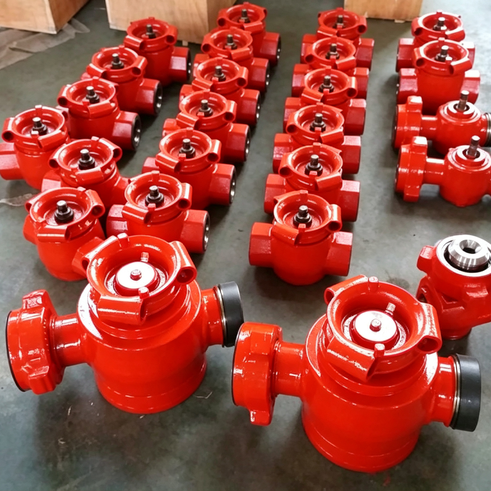
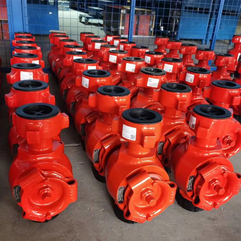
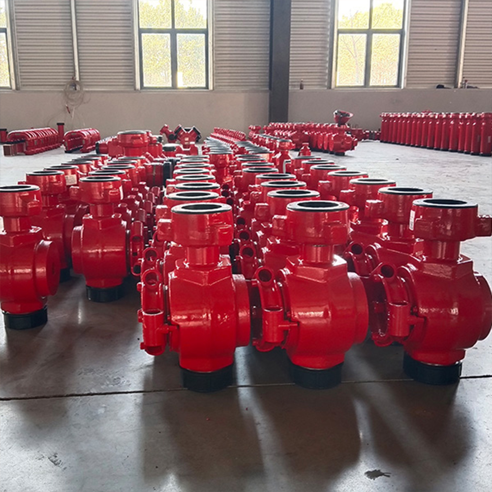
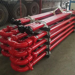
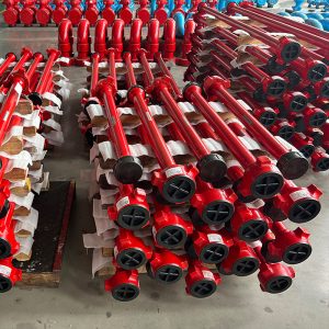
GPE manufactures High-Pressure Plug Valves for hydraulic fracturing, cementing, acidizing, well testing, circulation, pressure-control manifolds and abrasive flowback operations.
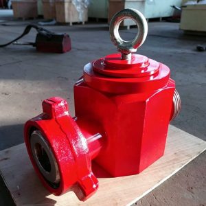
The valve uses a compact quarter-turn isolation structure with a forged alloy-steel pressure body, pressure-balanced plug, replaceable insert set and model-specific sealing system. A 90-degree operating movement changes the valve from fully open to fully closed, providing rapid isolation of high-pressure Flow Iron sections.
The full-bore flow path maintains the line ID through the valve and reduces abrupt restrictions in high-rate pumping systems. The pressure-balanced construction controls operating torque under differential pressure, while the replaceable insert and sealing components support field redressing and repeated service.
GPE manufactures Plug Valves in nominal sizes from 1 to 4 inches and working-pressure classes from 6,000 to 20,000 psi. Standard manufacturing configurations include:
- Manual bar or wrench operation
- Handwheel and gear operation
- Hydraulic actuation
- Pneumatic actuation
- Electric actuation
- High-pressure hammer-union ends
- API flanged ends
- Hub connections
- LP and TBG threaded connections
- Standard Service
- Low-Temperature Service
- H₂S and Sour Service
- Full-bore and project-specific bore configurations
- Replacement-compatible dimensions for existing Flow Iron systems
- Complete insert, seal and redress kits
Need a High-Pressure Plug Valve for Your Flow Iron System?
GPE manufactures High-Pressure Plug Valves according to the required size, working pressure, bore, end connection, actuation method and service environment.
Send us your existing part number, technical drawing or operating requirements. Our engineering team will prepare the matching valve configuration, dimensional proposal and factory quotation.
Request a Plug Valve Quote:
https://gpepump.com/contact/
Send Your Plug Valve Drawing:
info@gpepump.com
Product Short Description
GPE High-Pressure Plug Valves provide fast, low-torque shutoff for well-service Flow Iron and pressure-control manifold systems.
The valve body is machined from a heat-treated alloy-steel forging. The internal pressure-balanced plug rotates between replaceable inserts to open or isolate the full-bore flow path. The design controls operating torque, protects the primary sealing surfaces and simplifies replacement of wear components after abrasive or corrosive service.
Manual, geared, hydraulic, pneumatic and electric operating systems are supplied for local or remote valve control. The valve is used as an isolation valve and is operated in the fully open or fully closed position.
Product Highlights
- Nominal sizes from 1 to 4 in
- Working pressures from 6,000 to 20,000 psi
- Metric pressure classes from 42 to 140 MPa
- Quarter-turn opening and closing
- Compact low-torque valve structure
- Full-bore internal flow path
- Pressure-balanced plug design
- Replaceable insert set
- Replaceable stem, seal and packing components
- Forged alloy-steel pressure body
- Controlled quenching and tempering
- CNC-machined bore and sealing surfaces
- High resistance to pressure pulsation
- High resistance to mechanical vibration
- High resistance to abrasive Flow Iron service
- Manual bar-cap operation
- Manual handwheel operation
- Gearbox operation
- Hydraulic actuation
- Pneumatic actuation
- Electric actuation
- Local and remote operating configurations
- Position indication
- High-pressure hammer-union connections
- API flange connections
- Hub connections
- LP and TBG threaded connections
- Standard Service
- Low-Temperature Service
- H₂S and Sour Service
- PU and PL temperature classes
- NACE MR0175 / ISO 15156 material selection
- Heat-number and serial-number traceability
- Forging ultrasonic inspection
- Magnetic-particle inspection
- Hardness inspection
- Hydrostatic body testing
- Seat and closure testing
- Operating-function testing
- Complete redress-kit supply
- Replacement-compatible manufacturing
Main Technical Specifications
| Parameter | GPE Manufacturing Range |
|---|---|
| Product | High-Pressure Plug Valve |
| Product category | High-Pressure Flow Iron and Pressure-Control Valve |
| Valve function | Quarter-turn isolation |
| Nominal sizes | 1, 2, 3 and 4 in |
| Working pressure | 6,000–20,000 psi |
| Metric pressure class | 42–140 MPa |
| Pressure series | 6K, 10K, 15K and 20K |
| Standard temperature range | -29°C to 121°C |
| Low-temperature range | -46°C to 121°C |
| Temperature classes | PU and PL |
| Service environment | Standard, Low Temperature or H₂S Service |
| Bore | Full bore or approved project bore |
| Body construction | Forged and heat-treated alloy steel |
| Plug design | Pressure-balanced quarter-turn plug |
| Internal wear components | Replaceable insert set |
| Stem system | Model-specific sealed stem and operating mechanism |
| Operating methods | Bar, handwheel, gearbox, hydraulic, pneumatic or electric |
| Operating positions | Fully open or fully closed |
| Position indication | Mechanical or actuator-mounted indication |
| End connections | Hammer union, API flange, hub, LP thread or TBG thread |
| End combinations | Union × Union, Flange × Flange, Hub × Hub, Thread × Thread and mixed ends |
| Main applications | Fracturing, cementing, acidizing, well testing, circulation and flowback |
| H₂S material selection | NACE MR0175 / ISO 15156 |
| API configuration | API Spec 6A requirements for applicable flanged and hub valve configurations |
| Inspection | UT, MPI, hardness, dimensional and functional inspection |
| Pressure testing | Hydrostatic body, closure and seal-integrity testing |
| Supply scope | Complete valve, insert set, seal kit, actuator and redress parts |
Confirm the Correct Plug Valve Configuration
GPE manufactures standard and replacement-compatible High-Pressure Plug Valves from approved drawings, connection dimensions, existing part numbers and physical samples.
Send the valve size, pressure class, bore, connection, actuation method, service condition and quantity. We will confirm the correct configuration and provide the dimensional drawing and factory quotation.
Get the Correct Plug Valve Model:
https://gpepump.com/contact/
Send Plug Valve Specifications:
info@gpepump.com
Pressure and Service Classes
| Working Pressure | Metric Class | Main Service Positioning |
| 6,000 psi | 42 MPa | Cementing, circulation, testing and medium-pressure well service |
| 10,000 psi | 70 MPa | High-pressure cementing, acidizing, testing and manifold isolation |
| 15,000 psi | 105 MPa | Hydraulic fracturing, abrasive Flow Iron and pressure-pumping systems |
| 20,000 psi | 140 MPa | Ultra-high-pressure pumping, testing and engineered manifold systems |
The complete valve pressure rating is controlled by the lowest-rated pressure-containing component, end connection, actuator interface and service configuration.
Standard Size and Pressure Matrix
| Nominal Size | 6K | 10K | 15K | 20K |
| 1 in | ● | ● | ● | ● |
| 2 in | ● | ● | ● | ● |
| 3 in | ● | ● | ● | ● |
| 4 in | ● | ● | ● | ● |
The approved GPE drawing defines:
- Valve bore
- Face-to-face or end-to-end dimension
- Overall height
- Operating-stem dimensions
- Union, flange, hub or thread geometry
- Minimum pressure-body wall thickness
- Plug and insert dimensions
- Actuator mounting interface
- Product weight
- Lifting and handling points
Pressure-Balanced Plug Design
GPE uses a pressure-balanced plug structure to control the hydraulic force acting on the plug and stem during operation.
The pressure-balancing arrangement:
- Reduces operating torque
- Supports quarter-turn operation
- Controls uneven loading on the insert set
- Improves opening and closing stability
- Reduces stem and operator loading
- Supports manual or actuator operation
- Protects sealing contact during pressure cycling
The valve is operated through 90 degrees between the fully open and fully closed positions.
Full-Bore Flow Path
The full-bore configuration maintains a continuous flow area through the valve.
This design provides:
- Reduced pressure loss
- Reduced local flow velocity peaks
- Reduced turbulence at bore transitions
- Improved proppant transport
- Improved cement-slurry transport
- Easier flushing after service
- Reduced solids accumulation
- Direct passage for inspection and cleaning tools
The plug port is aligned with the valve bore in the fully open position. In the closed position, the plug blocks the flow path and isolates the downstream line.
Isolation Valve — Not a Choke Valve
The GPE High-Pressure Plug Valve is an isolation valve.
It is operated in either:
- Fully open position
- Fully closed position
The valve is not held in a partially open position to control flow rate or pressure.
Partial opening concentrates high-velocity fluid and abrasive solids across the plug port and insert edges. This creates rapid washout, seal damage, excessive operating torque and premature valve failure.
Flow regulation and pressure reduction are performed with a purpose-designed choke valve.
Replaceable Insert Set
The insert set is installed between the valve body and plug.
It provides:
- Controlled sealing contact
- Replaceable wear surfaces
- Plug support
- Pressure isolation
- Protection of the forged valve body
- Simplified field and workshop redressing
The inserts are manufactured, matched and inspected as a set. A used insert from one set is not mixed with a component from another set.
After disassembly, the insert set is inspected for:
- Erosion
- Cracking
- Deformation
- Seal-groove damage
- Chemical attack
- Surface scoring
- Excessive wear
- Loss of dimensional fit
Plug and Stem Assembly
The plug and stem assembly transfers operating torque from the bar cap, gearbox or actuator to the internal closure member.
The assembly provides:
- Quarter-turn movement
- Defined open and closed positions
- Accurate plug-port alignment
- Stem sealing
- Mechanical position indication
- Actuator connection
- Controlled operating load
The stem and operating interface are inspected for:
- Torsional deformation
- Thread damage
- Key or drive damage
- Seal-area wear
- Corrosion
- Excessive operating clearance
- Incorrect open and closed alignment
Sealing System
The sealing system contains pressure around the plug, inserts and operating stem.
The assembly includes:
- Insert sealing surfaces
- Plug sealing surfaces
- Stem seals
- Body seals
- Backup and anti-extrusion elements
- Lubricant or sealant passages
- Pressure-containing closure seals
The selected seal package is matched to:
- Working pressure
- Temperature class
- Fracturing fluid
- Cement slurry
- Acid system
- Hydrocarbon fluid
- H₂S exposure
- CO₂ exposure
- Chemical additives
Low-Torque Operation
The compact plug geometry, pressure-balanced design, precision-machined inserts and controlled operating clearances reduce the torque required to open and close the valve.
Operating torque is monitored during assembly and final function testing.
A sudden increase in operating torque identifies:
- Solids trapped around the plug
- Inadequate lubrication
- Insert damage
- Stem corrosion
- Plug scoring
- Pressure imbalance
- Incorrect assembly
- Excessive actuator loading
The valve is not forced through abnormal resistance. It is isolated, depressurized and inspected.
Manual Bar-Cap Operation
The manual bar-cap configuration provides direct quarter-turn operation through a removable operating bar or wrench.
It is used for:
- Compact Flow Iron layouts
- Frac Pump discharge lines
- Portable treatment lines
- Well-test packages
- Field-repairable systems
- Applications requiring minimum valve height
The operator remains outside the direction of pressurized connections and follows the approved site isolation procedure.
Handwheel and Gear Operation
The handwheel and gearbox configuration reduces the input force required for larger valves and high-pressure applications.
It provides:
- Controlled opening and closing
- Stable operator input
- Positive open and closed positions
- Clear position indication
- Reduced manual effort
- Adaptation to elevated or guarded valve locations
The gearbox is selected according to valve size, pressure class and required operating torque.
Hydraulic Actuation
The hydraulic actuator provides remote valve opening and closing for high-pressure pumping systems.
It is used in:
- Frac Pump discharge manifolds
- Frac Missiles
- Zipper Manifolds
- Pressure-control skids
- Remote isolation systems
- Red-Zone reduction programs
The hydraulic operating package includes:
- Actuator
- Mounting adapter
- Mechanical drive
- Open and closed stops
- Position indication
- Hydraulic ports
- Manual override
- Hose and fitting interfaces
The actuator is sized to exceed the specified valve operating torque with the project safety margin.
Pneumatic and Electric Actuation
Pneumatic and electric actuators are integrated into automated manifold and test systems.
The actuation package includes:
- Valve mounting bracket
- Drive coupling
- Open and closed travel limits
- Local position indication
- Remote position feedback
- Control connection
- Manual override
- Weather and environmental protection
The actuator control voltage, air pressure, hydraulic pressure, fail position and feedback signal are defined in the purchase specification.
Remote Control and Red-Zone Safety
Remote actuation reduces the need for personnel to approach pressurized Flow Iron during pumping and line switching.
A remote-control package provides:
- Open and closed commands
- Valve-position feedback
- Local manual override
- Emergency shutdown integration
- Interlock logic
- Sequential valve operation
- Pressure-based operating permissions
- Operating-event records
Remote operation supplements, rather than replaces, mechanical isolation, depressurization and site safety procedures.
End Connection Options
High-Pressure Hammer-Union Ends
Hammer-union ends provide rapid assembly and disassembly in temporary well-service Flow Iron.
They are used for:
- Fracturing lines
- Cementing lines
- Acidizing lines
- Pump discharge connections
- Flowback systems
- Well-test packages
The union figure, nominal size, pressure class, seal geometry, male or female orientation and service class are permanently identified.
API Flanged Ends
Flanged Plug Valves are integrated into:
- Wellhead systems
- Frac Trees
- Pressure-control manifolds
- Test skids
- Permanent piping packages
- API pressure-control equipment
API Spec 6A requirements are applied to flanged valve configurations ordered within the applicable wellhead, tree and pressure-control equipment scope.
Hub Connections
Hub-end valves provide compact high-pressure connections for manifold and skid integration.
The hub profile, clamp system, seal ring and pressure class follow the approved interface drawing.
LP and TBG Threaded Ends
LP and TBG threaded connections are manufactured for compatible oilfield piping and equipment interfaces.
The order specifies:
- Thread type
- Nominal size
- Pin or box orientation
- Thread gauge
- Pressure class
- Material and service condition
Standard Service
Standard-Service Plug Valves handle compatible non-sour fluids, including:
- Fracturing fluid
- Cement slurry
- Drilling fluid
- Completion brine
- Water
- Compatible oil-based fluids
- Well-test fluids
- Flowback fluids
Standard-Service pressure components and repair parts remain separated from H₂S Service components throughout manufacturing, marking, storage and maintenance.
Low-Temperature Service
GPE Low-Temperature Plug Valves use PL temperature-class materials and seals for operation from -46°C to 121°C.
Low-temperature manufacturing control includes:
- Qualified pressure-body material
- Controlled heat treatment
- Low-temperature impact testing
- Low-temperature elastomer selection
- Low-temperature lubricant selection
- Hardness verification
- Material traceability
The minimum design temperature is permanently stated on the product datasheet and nameplate.
H₂S and Sour Service
GPE H₂S Service Plug Valves use:
- Controlled-hardness pressure-body materials
- Qualified heat-treatment procedures
- H₂S-compatible sealing materials
- Sour-service plug and insert materials
- Hardness inspection
- Full heat-number traceability
- NACE MR0175 / ISO 15156 material selection
The purchase specification defines:
- H₂S partial pressure
- CO₂ concentration
- Chloride concentration
- Fluid pH
- Maximum operating temperature
- Total system pressure
- Acid concentration
- Chemical additives
H₂S Service components are permanently marked and are not mixed with Standard-Service repair parts.
Hydraulic Fracturing Applications
GPE Plug Valves isolate:
- Frac Pump discharge lines
- Pump Discharge Manifolds
- Frac Missiles
- Zipper Manifolds
- Frac Trees
- High-pressure treatment lines
- Individual pump branches
- Pressure-test sections
The full-bore structure supports high-rate proppant transport. Replaceable inserts and redress kits reduce complete-valve replacement after normal wear.
Hydraulically actuated models provide remote isolation and line switching in multi-pump and multi-well fracturing systems.
Cementing Applications
Plug Valves are installed between:
- Cementing Units
- High-Pressure Pumps
- Cementing Manifolds
- Cement Heads
- Circulating Heads
- Wellhead connections
- Flush and displacement lines
The full-bore path supports cement-slurry movement and post-job flushing.
Cement is removed from the plug cavity, insert area and operating passages immediately after service.
Acidizing Applications
Acidizing Plug Valves use materials, seals and lubricants matched to:
- Acid type
- Acid concentration
- Corrosion inhibitor
- Operating temperature
- H₂S content
- CO₂ content
- Chloride concentration
The valve is flushed and neutralized immediately after acid service.
Well Testing and Flowback
Well-test and flowback service can contain:
- Formation sand
- Residual proppant
- Scale
- Completion debris
- Water
- Hydrocarbon liquids
- Gas
- Corrosive contaminants
Flowback valves receive scheduled inspection of:
- Plug
- Insert set
- Internal bore
- Stem seals
- Body cavity
- End connections
- Wall thickness
- Actuator interface
Frac Pump and Manifold Integration
GPE designs Plug Valves to match:
- Frac Pump outlet size
- Pump branch spacing
- Discharge-manifold connection
- Existing Fig-type Flow Iron
- Manifold bore
- Valve operating direction
- Skid layout
- Actuator mounting
- Maintenance clearance
- Remote-control architecture
The approved GA drawing confirms the valve orientation, connection centerlines, actuator envelope and service access.
Replacement-Compatible Manufacturing
GPE manufactures replacement Plug Valves and redress components from:
- Existing part numbers
- Approved drawings
- Connection schedules
- Measured dimensions
- Physical samples
- Valve photographs
- Existing seal and insert samples
Replacement verification covers:
- Nominal size
- Bore
- Working pressure
- End connection
- Face-to-face or end-to-end dimension
- Operating-stem interface
- Open and closed direction
- Insert dimensions
- Seal-kit dimensions
- Actuator mounting
- Standard or H₂S Service
For common SPM Flow Iron systems, GPE matches the approved dimensional interfaces, union connections and replacement-part dimensions stated in the confirmed replacement schedule.
Manufacturing Process
- Alloy-steel forging material verification
- Heat-number assignment and traceability
- Forging ultrasonic inspection
- Rough pressure-body machining
- Controlled quenching and tempering
- Mechanical-property testing
- Hardness inspection
- Internal bore machining
- Plug-cavity machining
- Insert-pocket machining
- Stem and bonnet-interface machining
- Union, flange, hub or thread machining
- Plug machining and heat treatment
- Insert-set machining
- Seal-groove machining
- Critical-area magnetic-particle inspection
- Dimensional and wall-thickness inspection
- Plug, insert and seal assembly
- Stem and operating-system assembly
- Lubrication and operating-torque inspection
- Hydrostatic body testing
- Closure and seat testing
- Operating-function testing
- Permanent product marking
- Documentation review
- Export packaging
Quality Control
GPE quality control includes:
- Raw-material certificate verification
- Chemical-composition verification
- Heat-number traceability
- Heat-treatment records
- Yield-strength testing
- Tensile-strength testing
- Elongation testing
- Low-temperature impact testing for PL orders
- Body hardness inspection
- H₂S Service hardness inspection
- Forging ultrasonic inspection
- Magnetic-particle inspection
- Internal-bore inspection
- Pressure-body wall-thickness inspection
- Plug and insert dimensional inspection
- Stem-interface inspection
- Seal-groove inspection
- Union-end inspection
- Flange and hub inspection
- Thread-gauge inspection
- Assembly-clearance inspection
- Operating-torque inspection
- Open and closed position inspection
- Hydrostatic body testing
- Closure and seat testing
- Final visual inspection
Pressure and Functional Testing
Every GPE Plug Valve receives:
- Pressure-body hydrostatic testing
- Closed-valve pressure testing
- Seat and sealing-system inspection
- Pressure-hold testing
- External leakage inspection
- Stem-seal inspection
- Open and closed operating test
- Position-indicator verification
- Post-test operating-torque inspection
The approved Inspection and Test Plan defines:
- Test medium
- Test pressure
- Pressure ramp
- Stabilization time
- Hold time
- Test direction
- Acceptance criteria
- Recording method
- Customer or third-party witness point
API Spec 6A Positioning
API Spec 6A applies to wellhead and tree equipment, including valves supplied within its defined scope.
GPE applies API Spec 6A design, material, inspection, testing, marking and documentation requirements to applicable flanged and hub Plug Valve configurations ordered for wellhead, tree or pressure-control equipment service.
Hammer-union Flow Iron Plug Valves for fracturing, cementing, acidizing and flowback are manufactured according to:
- Approved GPE engineering drawings
- Rated pressure class
- Customer purchase specification
- Required service environment
- Inspection and Test Plan
- Hydrostatic and closure-test procedures
The complete product is identified by the actual manufacturing standard stated in the purchase order and Certificate of Conformity.
Product Marking
Each Plug Valve is permanently marked with:
- GPE identification
- Product name
- Nominal size
- Working pressure
- Bore
- End connection
- Standard or H₂S Service
- PU or PL temperature class
- Valve serial number
- Body heat number
- Plug and insert traceability
- Manufacturing date
- Open and closed direction
- Flow direction when specified
- Applicable product standard
Product Documentation
The order documentation includes:
- Certificate of Conformity
- Product datasheet
- General arrangement drawing
- Dimensional drawing
- Material Test Certificate
- Heat-treatment record
- Mechanical-property report
- Hardness report
- Low-temperature impact report for PL orders
- Ultrasonic-inspection report
- Magnetic-particle-inspection report
- Dimensional-inspection report
- Wall-thickness report
- Hydrostatic body-test report
- Closure and seat-test report
- Operating-function report
- Serial-number traceability list
- Operation and maintenance manual
- Lubrication instructions
- Redress instructions
- Spare-parts list
- Packing list
Maintenance and Redressing
Routine maintenance includes:
- Cleaning the valve after service
- Operating the valve only after approved isolation
- Inspecting the internal bore
- Inspecting the plug port
- Inspecting the insert set
- Inspecting stem and body seals
- Inspecting operating torque
- Lubricating the valve with the specified product
- Inspecting union, flange, hub or thread connections
- Inspecting actuator mounting
- Verifying open and closed position indication
- Replacing worn inserts and soft seals
- Completing pressure testing after redressing
The valve remains in the fully open position during storage unless the approved GPE preservation procedure states otherwise.
Exposed threads and sealing surfaces receive corrosion protection and end protectors.
Redress Kits and Spare Parts
GPE supplies:
- Matched insert sets
- Plug assemblies
- Stem assemblies
- Primary seals
- Body seals
- Stem seals
- Backup and anti-extrusion rings
- Bonnet seals
- Retaining components
- Lubrication fittings
- Manual operating caps
- Handwheels
- Gearboxes
- Hydraulic actuators
- Pneumatic actuators
- Electric actuators
- Position indicators
- Complete seal kits
- Complete valve redress kits
Each redress kit is identified by valve model, nominal size, pressure class, service class and serial-number range.
Common Failure Modes
Valve Leakage in the Closed Position
Primary causes:
- Worn insert set
- Plug scoring
- Solids trapped on the sealing surface
- Seal damage
- Chemical attack
- Incorrect assembly
- Plug not fully closed
Corrective action:
- Isolate and depressurize the valve
- Disassemble the pressure boundary
- Inspect the plug and matched insert set
- Replace damaged inserts and seals
- Verify full closed alignment
- Pressure-test before returning to service
High Operating Torque
Primary causes:
- Inadequate lubrication
- Solids trapped around the plug
- Insert deformation
- Plug scoring
- Stem corrosion
- Pressure imbalance
- Misaligned actuator
- Incorrect assembly clearance
Corrective action:
- Stop operation
- Isolate and depressurize the system
- Inspect the operating mechanism
- Clean the valve cavity
- Inspect the plug, inserts and stem
- Replace damaged components
- Complete function and pressure testing
Stem Leakage
Primary causes:
- Worn stem seals
- Damaged stem sealing surface
- Excessive stem movement
- Chemical incompatibility
- Incorrect seal installation
- Pressure cycling
Corrective action:
- Isolate and depressurize the valve
- Replace the complete stem-seal set
- Inspect the stem sealing surface
- Verify operating clearance
- Complete pressure testing
Rapid Internal Washout
Primary causes:
- Valve held partially open
- Excessive flow velocity
- High proppant concentration
- Abrasive flowback
- Plug not aligned in the open position
- Damaged insert edges
Corrective action:
- Operate the valve only fully open or fully closed
- Replace the plug and insert set
- Verify full-open alignment
- Review the valve size and bore
- Establish scheduled internal inspection
External Connection Leakage
Primary causes:
- Incorrect union or flange interface
- Damaged seal ring
- Worn metal sealing surface
- Incorrect makeup
- Thread damage
- Service-class mismatch
- End-connection erosion
Corrective action:
- Isolate and depressurize the line
- Inspect the complete connection
- Replace the seal
- Verify the connection figure and service class
- Repair or replace damaged pressure components
- Pressure-test before service
Why Service Companies and Equipment Integrators Select GPE
Pressure-Pumping and Fracturing Companies
GPE provides:
- Full-bore 15K and 20K isolation
- Low-torque quarter-turn operation
- Replaceable inserts and seal kits
- Hydraulic remote actuation
- Replacement-compatible dimensions
- Rapid redressing
- Long-term spare-parts supply
Flow Iron Rental and Repair Companies
GPE provides:
- Model-specific redress kits
- Serial-number traceability
- Replaceable wear components
- Operating and maintenance instructions
- Pressure-test documentation
- Replacement-part schedules
- Custom manufacturing from existing samples
Equipment Manufacturers and System Integrators
GPE provides:
- GA drawings
- Connection-interface drawings
- Actuator mounting data
- Valve orientation drawings
- 3D model support
- Skid and manifold integration
- Manual and remote actuation
- FAT and third-party inspection
Oil and Gas Operators
GPE provides:
- High-pressure isolation
- Remote valve control
- Position feedback
- Red-Zone exposure reduction
- Complete manufacturing records
- H₂S and low-temperature configurations
- Maintenance and recertification support
How to Select the Correct Plug Valve
- Select the nominal flowline size.
- Select the required full-bore ID.
- Select the rated working pressure.
- Define the end connection.
- Define the male, female, flange, hub or thread orientation.
- Select manual, geared, hydraulic, pneumatic or electric actuation.
- Define the operating direction.
- Define Standard, Low-Temperature or H₂S Service.
- State the minimum and maximum operating temperature.
- State the service fluid and chemical composition.
- State the maximum flow rate.
- State the proppant concentration and particle size.
- Provide the required end-to-end dimensions.
- Provide the existing part number or drawing for replacement orders.
- Define inspection, testing and documentation requirements.
- Define spare insert, seal and redress-kit quantities.
Frequently Asked Questions
What High-Pressure Plug Valve sizes does GPE manufacture?
GPE manufactures 1, 2, 3 and 4 in High-Pressure Plug Valves.
What working-pressure classes are available?
GPE manufactures 6,000, 10,000, 15,000 and 20,000 psi pressure classes.
Is the valve full bore?
Yes. GPE manufactures full-bore Plug Valves that maintain a continuous flow path through the valve in the fully open position.
How does the valve open and close?
The pressure-balanced plug rotates through 90 degrees between the fully open and fully closed positions.
Is the Plug Valve used for throttling?
No. It is an isolation valve and is operated fully open or fully closed. Flow regulation is performed with a choke valve.
Why is the valve described as low torque?
The pressure-balanced plug, precision-machined insert set and controlled operating clearances reduce the hydraulic and mechanical force required to operate the valve.
What operating methods are available?
GPE supplies:
- Manual bar operation
- Handwheel operation
- Gearbox operation
- Hydraulic actuation
- Pneumatic actuation
- Electric actuation
Can GPE supply remote hydraulic Plug Valves?
Yes. GPE supplies hydraulically actuated Plug Valves with mounting adapters, position indication, manual override and control-system interfaces.
Which connection is used for 15,000 psi fracturing Flow Iron?
Fig 1502 hammer-union configurations are widely used for 15,000 psi fracturing Flow Iron. GPE manufactures the connection and end orientation stated in the approved drawing.
Are flanged Plug Valves available?
Yes. GPE manufactures API flanged Plug Valves for wellhead, Frac Tree, manifold and pressure-control equipment integration.
Are hub connections available?
Yes. GPE manufactures compact hub-end Plug Valves according to the approved hub, clamp and seal-ring interface.
Are LP and TBG thread connections available?
Yes. LP and TBG threaded connections are manufactured in the required size, pin or box orientation and pressure class.
What is the standard temperature range?
The PU temperature class covers -29°C to 121°C.
What is the low-temperature range?
The PL temperature class covers -46°C to 121°C.
What is the difference between Standard and H₂S Service?
H₂S Service uses controlled-hardness materials, qualified heat treatment, H₂S-compatible seals, hardness inspection and NACE MR0175 / ISO 15156 material selection.
Does API Spec 6A apply to every GPE Plug Valve?
API Spec 6A requirements apply to applicable flanged and hub Plug Valves ordered within the wellhead, tree and pressure-control equipment scope.
Hammer-union Flow Iron Plug Valves are manufactured according to GPE drawings, the stated pressure class, service requirements and purchase specification.
Can the valve handle proppant-laden fracturing fluid?
Yes. The forged full-bore valve, pressure-balanced plug and replaceable insert set are manufactured for abrasive well-service Flow Iron.
The inspection and redress interval is controlled by flow rate, proppant loading, particle size and pumping history.
Can GPE manufacture replacement-compatible Plug Valves?
Yes. GPE manufactures replacement valves from approved drawings, existing part numbers, measured dimensions and physical samples.
Are SPM replacement configurations available?
Yes. GPE manufactures replacement configurations for confirmed SPM Flow Iron interfaces according to the approved dimensional and replacement-part schedule.
Are insert and seal kits supplied?
Yes. GPE supplies matched insert sets, pressure seals, stem seals, backup rings and complete model-specific redress kits.
What testing is completed before shipment?
Every valve receives hydrostatic body testing, closed-valve pressure testing, seal inspection, operating-function testing and final visual inspection.
Request a High-Pressure Plug Valve Quotation
GPE manufactures complete High-Pressure Plug Valves and replacement components for fracturing, cementing, acidizing, well testing, circulation, pressure-control manifold and flowback systems.
Our manufacturing range includes:
- 1–4 in nominal sizes
- 6,000–20,000 psi pressure ratings
- Full-bore pressure-balanced design
- Manual, geared and actuated operation
- Hammer-union, API flange, hub, LP and TBG connections
- Standard, Low-Temperature and H₂S Service
- PU and PL temperature classes
- Replacement-compatible dimensions
- Complete material and pressure-test documentation
- Insert, seal, actuator and redress kits
Send the required size, pressure rating, bore, connection, actuation method, service environment, temperature, dimensions and quantity to receive the correct technical proposal.
Request a Technical Quote:
https://gpepump.com/contact/
Email:
info@gpepump.com
Reviews
There are no reviews yet.