

Description
Product Overview
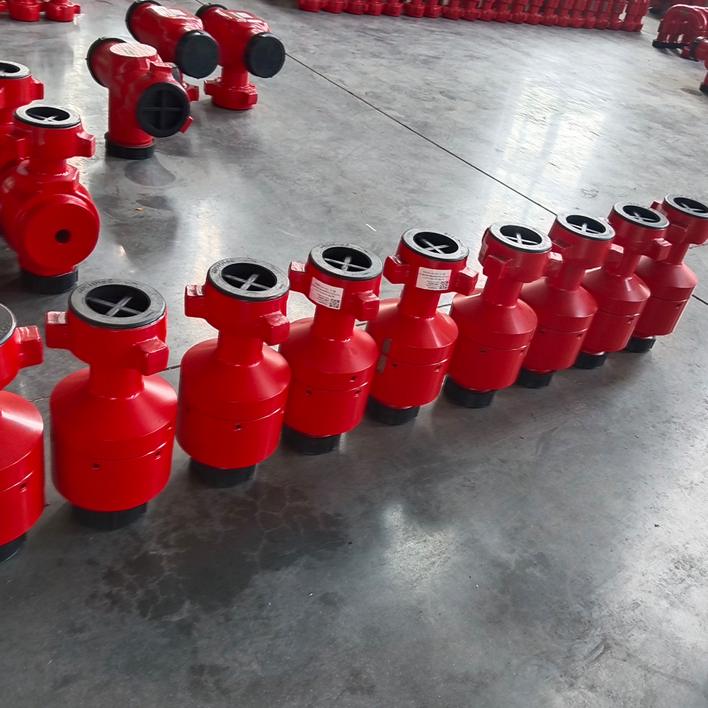
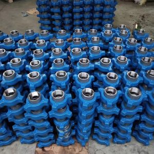
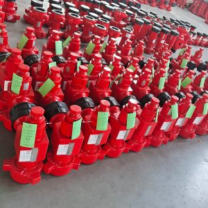
GPE manufactures High-Pressure Check Valves for hydraulic fracturing, cementing, acidizing, well testing, circulation, pressure-pumping and abrasive flowback systems.
The valve allows fluid to move in the specified forward direction and automatically closes when flow stops or reverses. This prevents downstream pressure and fluid from returning toward Frac Pumps, plunger pumps, fluid ends, pump discharge manifolds and other upstream equipment.
GPE manufactures three principal structures:
- In-Line Swing / Flapper Check Valve
- Top-Entry Flapper Check Valve
- Dart-Type Spring Check Valve
The manufacturing range covers 2, 3 and 4 in nominal sizes with working-pressure classes from 6,000 to 20,000 psi. Standard configurations include high-pressure hammer-union ends, API flanged ends, male-to-female or female-to-male flow orientation, Standard Service and H₂S Service.
The forged alloy-steel pressure body, replaceable internal closure components and precision-machined sealing surfaces provide stable non-return performance under pressure pulsation, pump shutdown, manifold switching and high-pressure flowline operation.
GPE Check Valves are installed with related High-Pressure Plug Valves, High-Pressure Swivel Joints, Emergency Relief Valves and complete Flowline & Frac Manifold systems.
Need a Check Valve for Your Frac Pump or Flow Iron System?
Send GPE the required size, working pressure, valve structure, flow direction, end connection, service condition and quantity. Our engineering team will confirm the correct non-return valve configuration and provide a factory quotation.
Request a Check Valve Quote:
https://gpepump.com/contact/
Send Your Check Valve Drawing:
info@gpepump.com
Product Short Description
GPE High-Pressure Check Valves provide automatic backflow protection for Frac Pumps, plunger pumps, pump discharge lines, treatment manifolds and temporary Flow Iron.
Forward pressure opens the internal flapper or dart and allows fluid to pass through the valve. When forward flow decreases, stops or reverses, the closure element returns to the seat and blocks reverse pressure from reaching upstream equipment.
In-Line Swing models provide a compact low-restriction flow path. Top-Entry models allow internal parts to be serviced after the line has been isolated without removing the complete body from the flowline. Dart-Type models use a spring-loaded axial closure for rapid response and controlled closing.
Product Highlights
- Automatic non-return protection
- Prevents reverse fluid and pressure flow
- Protects Frac Pumps and plunger-pump fluid ends
- Isolates inactive parallel pump branches
- Nominal sizes from 2 to 4 in
- Working pressures from 6,000 to 20,000 psi
- Metric pressure classes from 42 to 140 MPa
- In-Line Swing / Flapper design
- Top-Entry Flapper design
- Dart-Type spring-assisted design
- Forged alloy-steel pressure body
- Controlled quenching and tempering
- CNC-machined flow bores and sealing surfaces
- Replaceable flapper, dart, seat, spring and seal components
- Compact in-line structure
- Full-opening flapper flow path
- Service-in-place top-entry construction
- Rapid spring-assisted dart closure
- Female-to-Male flow orientation
- Male-to-Female reverse-flow orientation
- High-pressure hammer-union connections
- API flanged connections
- Standard Service
- H₂S and Sour Service
- PU temperature class from -29°C to 121°C
- NACE MR0175 / ISO 15156 material selection
- Forging ultrasonic inspection
- Magnetic-particle inspection
- Hardness inspection
- Hydrostatic body testing
- Reverse-pressure closure testing
- Functional opening and closing testing
- Complete internal and redress kits
- Replacement-compatible manufacturing
Main Technical Specifications
| Parameter | GPE Manufacturing Range |
|---|---|
| Product | High-Pressure Check Valve |
| Alternative name | Non-Return Valve |
| Product category | High-Pressure Flow Iron and Pressure-Control Valve |
| Valve function | Allows forward flow and prevents reverse flow |
| Nominal sizes | 2, 3 and 4 in |
| Working pressure | 6,000–20,000 psi |
| Metric pressure class | 42–140 MPa |
| Pressure series | 6K, 10K, 15K and 20K |
| Working temperature | -29°C to 121°C |
| Temperature class | PU |
| Service environment | Standard Service or H₂S Service |
| Available structures | In-Line Swing, Top-Entry Flapper and Dart Type |
| Body construction | Forged and heat-treated alloy steel |
| In-Line closure | Hinged flapper or spring-loaded dart |
| Top-Entry closure | Replaceable flapper assembly |
| Dart mechanism | Axial dart, guide, spring and seat |
| Flow direction | Female-to-Male or Male-to-Female |
| Internal flow path | Model-specific full-opening or axial flow path |
| End connections | Hammer union and API flange |
| Main applications | Fracturing, cementing, acidizing, testing, circulation and flowback |
| H₂S material selection | NACE MR0175 / ISO 15156 |
| API configuration | API Spec 6A requirements for applicable flanged top-entry configurations |
| Inspection | UT, MPI, hardness, dimensional and functional inspection |
| Pressure testing | Hydrostatic body, forward-flow and reverse-closure testing |
| Supply scope | Complete valve, internal kit, seal kit and redress parts |
Confirm the Correct Check Valve Structure
The correct valve structure depends on flow rate, pressure class, allowable pressure loss, solids content, maintenance method, flow direction and installation space.
Send GPE the pump model, maximum flow rate, normal pressure, valve size, connection, flow direction and service fluid. We will confirm whether an In-Line Swing, Top-Entry Flapper or Dart-Type Check Valve provides the correct protection.
Get the Correct Check Valve Model:
https://gpepump.com/contact/
Send Check Valve Specifications:
info@gpepump.com
Standard Pressure Configurations
| Working Pressure | Metric Class | Typical System Position |
| 6,000 psi | 42 MPa | Cementing, circulation and medium-pressure service |
| 10,000 psi | 70 MPa | Acidizing, testing and high-pressure pumping |
| 15,000 psi | 105 MPa | Hydraulic fracturing and Fig 1502 Flow Iron |
| 20,000 psi | 140 MPa | Ultra-high-pressure pumping and engineered Flow Iron |
The complete valve pressure rating is controlled by the lowest-rated body, bonnet, closure component, end connection, seal system and service configuration.
Standard Size and Pressure Matrix
| Nominal Size | 6K | 10K | 15K | 20K |
| 2 in | ● | ● | ● | ● |
| 3 in | ● | ● | ● | ● |
| 4 in | ● | ● | ● | ● |
The approved manufacturing drawing defines:
- Internal bore
- Seat diameter
- Cracking-pressure range
- End-to-end dimension
- Overall height
- Closure geometry
- Union or flange interface
- Minimum wall thickness
- Product weight
- Flow-direction marking
What Is a High-Pressure Check Valve?
A High-Pressure Check Valve is an automatic non-return valve installed in a pressure-pumping line.
The valve opens when inlet pressure creates forward flow through the approved direction. When forward flow stops or downstream pressure becomes higher than upstream pressure, the closure element returns to the seat and blocks reverse flow.
The valve protects upstream equipment from:
- Reverse pressure
- Reverse fluid movement
- Pump-to-pump backflow
- Manifold pressure migration
- Fluid-end reverse loading
- Pressure transfer into an inactive pump branch
- Uncontrolled return flow after pump shutdown
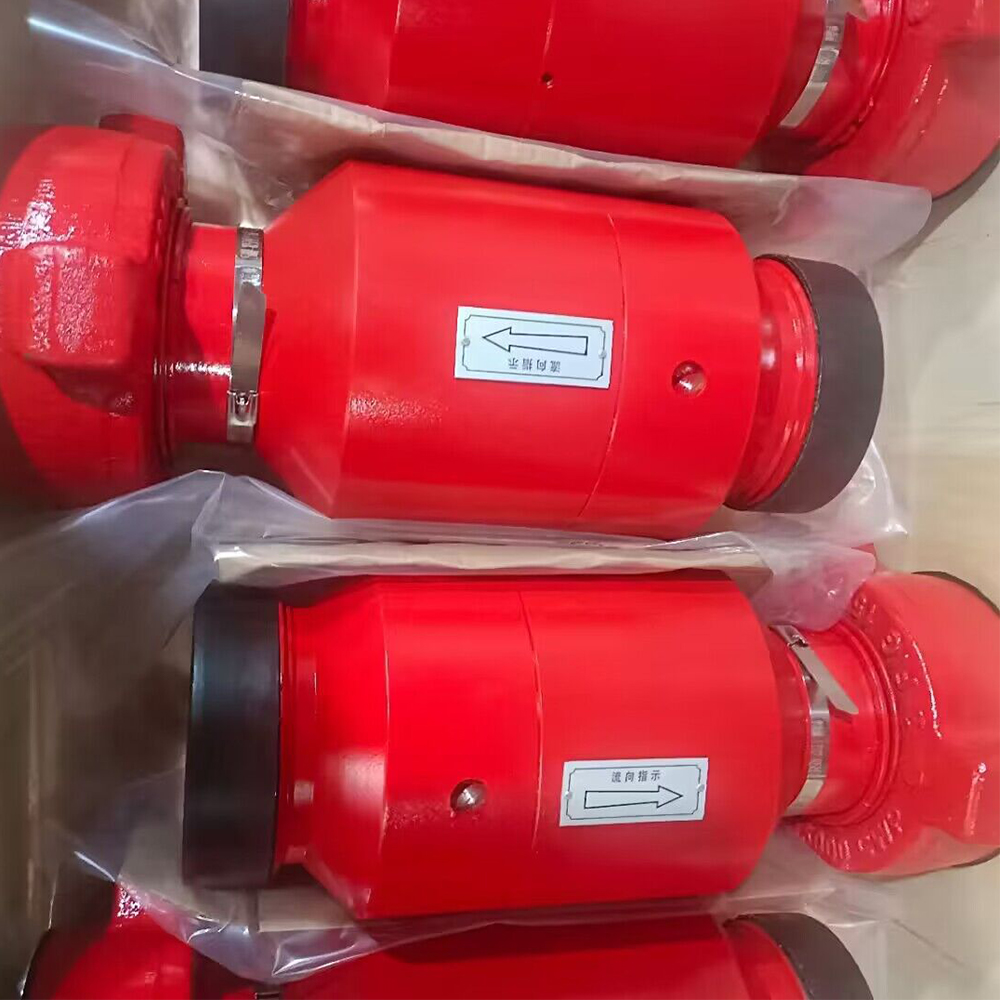
The arrow marked on the valve body identifies the permitted forward-flow direction.
Check Valve Working Principle
Forward Flow
Forward pressure acts on the flapper or dart.
When the inlet-to-outlet differential pressure exceeds the opening force, the closure element moves away from the seat and fluid passes through the valve.
Flow Reduction
As forward flow decreases, the closure element moves toward the seat under gravity, spring force or reverse differential pressure.
Reverse Flow
When outlet pressure exceeds inlet pressure, reverse pressure forces the flapper or dart firmly against the seat.
The closed valve blocks pressure and fluid from returning toward the pump or upstream equipment.
Pressure Equalization
A seated Check Valve can trap pressure between the valve and another closed isolation valve.
Both sides of the valve are safely vented and verified at zero pressure before inspection, bonnet removal or internal servicing.
In-Line Swing / Flapper Check Valve
The In-Line Swing Check Valve uses a hinged flapper installed inside a compact two-piece pressure body.
Forward flow rotates the flapper away from the seat and opens the flow path. When flow stops or reverses, reverse pressure returns the flapper to the seat and prevents backflow.
In-Line Swing Advantages
- Compact end-to-end dimensions
- Large open flow area
- Low pressure loss
- Reduced normal-flow restriction
- Simple closure movement
- Suitable for high flow rates
- Replaceable internal flapper and seals
- Suitable for temporary Flow Iron
Main Applications
- Frac Pump discharge branches
- Pump Discharge Manifolds
- Cementing lines
- Acidizing lines
- Well-test flowlines
- High-pressure circulation systems
- Flowback lines
The In-Line Swing design is selected where low restriction and compact installation are primary requirements.
Top-Entry Flapper Check Valve
The Top-Entry Check Valve uses a removable bonnet above the flow bore.
After the system has been isolated, depressurized and verified safe, the bonnet is removed and the internal flapper, seat and seals are serviced without removing the complete valve body from the flowline.
Top-Entry Advantages
- Internal servicing without removing the body from the line
- Reduced maintenance disassembly
- Fast replacement of wear components
- Clear access to flapper and seat
- Robust structure for portable treatment lines
- Lifting eye for controlled bonnet handling
- Hammer-union or flanged connections
- Suitable for Standard and H₂S Service
Main Applications
- Portable high-pressure flowlines
- Frac Pump manifold systems
- Cementing skids
- Well-test packages
- Pressure-control manifolds
- Choke-and-kill equipment
- Long-duration field service
The top-entry design reduces maintenance time where the valve body is integrated into a manifold or rigid flowline.
Dart-Type Check Valve
The Dart-Type Check Valve uses an axial dart, spring, guide and seat.
Forward pressure pushes the dart away from the seat and compresses the spring. When forward flow decreases or reverses, the spring drives the dart back into the seat.
Dart-Type Advantages
- Rapid spring-assisted closing
- Controlled axial movement
- Compact body structure
- Positive closure at low flow
- Stable installation in horizontal or vertical lines
- Replaceable dart, spring and seat
- Directional flow control
Dart-Type Flow Consideration
The dart and spring remain inside the normal flow path. This creates more forward-flow restriction than a full-opening swing or flapper design.
The Dart-Type Check Valve is selected where rapid closure and positive spring assistance are more important than minimum pressure loss.
Swing Check Valve vs Dart Check Valve
| Swing / Flapper Type | Dart Type |
| Hinged flapper moves out of the primary flow path | Axial dart remains in the central flow path |
| Larger open flow area | More controlled spring-assisted closing |
| Lower normal-flow pressure loss | Higher normal-flow restriction |
| Suitable for high-rate fracturing and cementing | Suitable for rapid closure and defined cracking pressure |
| Gravity and reverse pressure assist closure | Spring and reverse pressure assist closure |
| Flapper and seat are primary wear components | Dart, guide, spring and seat are primary wear components |
Top-Entry vs In-Line Check Valve
| Top-Entry Check Valve | In-Line Check Valve |
| Internal components accessed through a removable bonnet | Body is opened through the in-line body connection |
| Body remains installed during internal maintenance | Valve is normally removed or body sections separated |
| Larger external envelope | Compact external envelope |
| Suitable for manifold and skid integration | Suitable for temporary compact Flow Iron |
| Flapper structure | Flapper or dart structure |
| Hammer-union and API flanged ends | Primarily hammer-union ends |
Cracking Pressure
Cracking pressure is the forward differential pressure required to begin opening the valve.
The required cracking pressure is controlled by:
- Closure weight
- Spring force
- Seat diameter
- Flapper or dart geometry
- Installation orientation
- Fluid density
- Seal friction
- Service temperature
GPE machines and assembles each model to the approved cracking-pressure range.
A cracking pressure that is too high increases pump load and pressure loss. A cracking pressure that is too low can cause unstable closure, vibration or reverse leakage.
Reverse-Pressure Sealing
Reverse pressure acts on the closure element and forces it against the seat.
The reverse-pressure sealing system includes:
- Flapper or dart sealing surface
- Replaceable seat
- Body and bonnet seals
- Guide components
- Spring components for dart designs
- Retaining and locking components
The reverse-pressure rating is equal to the approved valve working-pressure rating after successful body and closure testing.
Full-Opening Flapper Flow Path
In swing and top-entry designs, the flapper moves away from the primary bore during forward flow.
This provides:
- Large flow area
- Reduced pressure loss
- Reduced local velocity increase
- Improved proppant transport
- Improved cement-slurry transport
- Reduced solids accumulation
- Easier flushing
The open flapper position is controlled to prevent impact damage and unstable movement under high flow.
Flow Direction and End Orientation
The standard Flow Iron arrangement is manufactured with Female-to-Male forward flow.
GPE also manufactures Male-to-Female reverse-flow configurations.
The approved drawing and body arrow define:
- Inlet connection
- Outlet connection
- Forward-flow direction
- Male and female orientation
- Installation direction
- Bonnet orientation
- Service access
The valve is never installed based only on connection appearance.
Fig 1502 Hammer-Union Configuration
The principal 15K configuration uses Fig 1502 hammer-union ends.
This configuration provides:
- Rapid field installation
- Compact Flow Iron connection
- Compatibility with fracturing lines
- Replaceable union seal
- Defined male and female orientation
- Pressure-rated mechanical connection
The valve integrates naturally with GPE Swivel Joints and Plug Valves in pump discharge and manifold assemblies.
Connection verification includes:
- Figure number
- Nominal size
- Male or female end
- Union thread geometry
- Seal-ring profile
- Working-pressure rating
- Standard or H₂S Service
- Dimensional compatibility
API Flanged Top-Entry Configuration
GPE manufactures flanged Top-Entry Check Valves for wellhead, tree, manifold and pressure-control equipment.
API Spec 6A requirements are applied to check-valve configurations ordered within the applicable wellhead and tree equipment scope.
The API configuration defines:
- Rated working pressure
- Nominal bore
- Flange size and type
- Material class
- Temperature class
- Product Specification Level
- Performance requirement
- Closure testing
- Marking and documentation
Hammer-union Flow Iron Check Valves for fracturing, cementing, acidizing and flowback are manufactured according to GPE drawings, the stated pressure class, service conditions and purchase specification.
Standard Service
Standard-Service Check Valves handle compatible non-sour fluids, including:
- Fracturing fluid
- Cement slurry
- Drilling fluid
- Completion brine
- Water
- Compatible oil-based fluids
- Well-test fluids
- Flowback fluids
Standard-Service pressure parts and repair components remain separated from H₂S Service components.
H₂S and Sour Service
GPE H₂S Service Check Valves use:
- Controlled-hardness pressure-body materials
- Qualified heat-treatment procedures
- H₂S-compatible seals
- Sour-service closure and seat materials
- Hardness inspection
- Full heat-number traceability
- NACE MR0175 / ISO 15156 material selection
The purchase specification states:
- H₂S partial pressure
- CO₂ concentration
- Chloride concentration
- Fluid pH
- Maximum operating temperature
- Total system pressure
- Acid concentration
- Chemical additives
H₂S Service components are permanently identified and are not mixed with Standard-Service repair parts.
Hydraulic Fracturing Applications
GPE Check Valves protect:
- Frac Pump fluid ends
- Individual pump discharge branches
- Pump Discharge Manifolds
- Frac Missiles
- Zipper Manifolds
- High-pressure treatment lines
- Pressure-test sections
- Standby pump branches
In a multi-pump Frac Spread, a Check Valve prevents manifold pressure from returning into a stopped or isolated pump branch.
The valve is installed upstream or downstream of the High-Pressure Plug Valve according to the approved manifold layout and isolation philosophy.
Cementing Applications
The Check Valve prevents cement slurry and displacement fluid from returning toward the cementing pump after pump shutdown.
It is installed in:
- Cementing-unit discharge lines
- Cementing manifolds
- High-pressure pump branches
- Cement-head supply lines
- Circulation lines
- Pressure-test lines
After cementing, the valve is flushed before slurry hardens around the flapper, dart, spring or seat.
Acidizing Applications
Acidizing Check Valves use pressure-body materials, seals and internal trim selected according to:
- Acid type
- Acid concentration
- Corrosion inhibitor
- Operating temperature
- H₂S exposure
- CO₂ exposure
- Chloride concentration
The valve is flushed and neutralized immediately after acid service.
Well Testing and Flowback
Well-test and flowback fluids can contain:
- Formation sand
- Residual proppant
- Scale
- Completion debris
- Water
- Hydrocarbon liquids
- Gas
- Corrosive contaminants
Flowback Check Valves receive scheduled inspection of:
- Flapper or dart
- Seat
- Spring
- Guide
- Internal bore
- Bonnet seal
- End connections
- Pressure-body wall thickness
Parallel Pump Protection
Check Valves are installed on parallel pump branches to prevent an operating pump from forcing pressure and fluid into a stopped pump.
This protection supports:
- Independent pump startup
- Independent pump shutdown
- Isolation of a failed pump branch
- Stable manifold pressure
- Reduced reverse loading on fluid-end valves
- Safer maintenance planning
- Controlled multi-pump operation
The Check Valve is not treated as the only isolation barrier. A dedicated Plug Valve or other approved isolation valve is used for maintenance isolation.
Check Valve and Plug Valve Functions
A Check Valve closes automatically when flow reverses.
A Plug Valve is manually or remotely operated to create positive line isolation.
The two products perform different duties:
- Check Valve: automatic backflow prevention
- Plug Valve: controlled isolation
- Emergency Relief Valve: overpressure protection
A complete high-pressure pump branch commonly uses all three products. GPE supplies matching Plug Valves and Emergency Relief Valves for integrated pressure-control layouts.
Trapped-Pressure Safety
A seated Check Valve can trap pressure between the Check Valve and a downstream Plug Valve or closed manifold valve.
Before maintenance:
- Stop the pressure source.
- Isolate the complete branch.
- Open the approved bleed point.
- Vent both sides of the Check Valve.
- Verify zero pressure on both sides.
- Confirm zero trapped pressure before removing the bonnet or body connection.
Loosening a union, flange or bonnet is not used as a pressure-bleeding method.
Forged Alloy-Steel Construction
GPE manufactures pressure-containing bodies from high-strength alloy-steel forgings.
Forged construction provides:
- Stable mechanical properties
- High pressure strength
- Resistance to pressure pulsation
- Resistance to mechanical impact
- High fatigue strength
- Controlled heat-treatment response
- Consistent wall thickness
- Reliable sealing and bonnet support
Internal closure components are manufactured from alloy steel, stainless steel or service-specific corrosion-resistant materials according to the approved design.
Manufacturing Process
- Alloy-steel forging material verification
- Heat-number assignment and traceability
- Forging ultrasonic inspection
- Rough body machining
- Controlled quenching and tempering
- Mechanical-property testing
- Hardness inspection
- Internal bore machining
- Seat-pocket machining
- Hinge, guide or dart-path machining
- Bonnet-interface machining
- Union or flange machining
- Flapper, dart, spring and seat manufacturing
- Seal-groove machining
- Critical-area magnetic-particle inspection
- Dimensional and wall-thickness inspection
- Closure-component assembly
- Bonnet or body assembly
- Functional opening and closing inspection
- Hydrostatic pressure-body testing
- Forward-flow functional testing
- Reverse-pressure closure testing
- External leakage inspection
- Permanent product marking
- Documentation review
- Export packaging
Quality Control
GPE quality control includes:
- Raw-material certificate verification
- Chemical-composition verification
- Heat-number traceability
- Heat-treatment records
- Yield-strength testing
- Tensile-strength testing
- Elongation testing
- Impact testing for specified low-temperature orders
- Body hardness inspection
- H₂S Service hardness inspection
- Forging ultrasonic inspection
- Magnetic-particle inspection
- Internal-bore inspection
- Pressure-body wall-thickness inspection
- Seat-pocket dimensional inspection
- Flapper-hinge inspection
- Dart and guide inspection
- Spring inspection
- Bonnet-interface inspection
- Union-end inspection
- Flange inspection
- Seal-groove inspection
- Assembly-clearance inspection
- Closure-movement inspection
- Hydrostatic body testing
- Reverse-pressure closure testing
- Final visual inspection
Pressure and Functional Testing
Every GPE Check Valve receives:
- Hydrostatic pressure-body test
- Body and bonnet external leakage inspection
- Forward opening test
- Closure movement test
- Reverse-pressure sealing test
- Pressure-hold test
- Flow-direction verification
- Post-test internal inspection
- Final marking inspection
The approved Inspection and Test Plan defines:
- Test medium
- Test pressure
- Pressure ramp
- Stabilization time
- Hold time
- Forward and reverse test direction
- Acceptance criteria
- Recording method
- Customer or third-party witness point
Product Marking
Each valve is permanently marked with:
- GPE identification
- Product name
- Valve structure
- Nominal size
- Working pressure
- Flow-direction arrow
- Inlet and outlet identification
- End connection
- Standard or H₂S Service
- Temperature class
- Valve serial number
- Body heat number
- Manufacturing date
- Applicable product standard
Product Documentation
The order documentation includes:
- Certificate of Conformity
- Product datasheet
- General arrangement drawing
- Connection drawing
- Material Test Certificate
- Heat-treatment record
- Mechanical-property report
- Hardness report
- Ultrasonic-inspection report
- Magnetic-particle-inspection report
- Dimensional-inspection report
- Wall-thickness report
- Hydrostatic body-test report
- Reverse-pressure closure-test report
- Functional-test report
- Serial-number traceability list
- Installation instructions
- Operation and maintenance manual
- Redress instructions
- Spare-parts list
- Packing list
Installation Requirements
Before installation:
- Confirm the valve model and pressure class
- Confirm the flow-direction arrow
- Confirm the male and female connection orientation
- Inspect union or flange sealing surfaces
- Install the correct seal ring
- Confirm line alignment
- Support the valve and adjacent Flow Iron
- Confirm bonnet service clearance
- Confirm bleed and depressurization points
- Confirm Standard or H₂S Service compatibility
The valve is installed with the body arrow pointing in the required forward-flow direction.
Routine Maintenance
Routine maintenance includes:
- Cleaning the complete valve after service
- Inspecting flow-direction marking
- Inspecting external leakage
- Inspecting union or flange connections
- Verifying closure movement after depressurization
- Inspecting the flapper, dart and seat
- Inspecting spring condition
- Inspecting hinge and guide components
- Inspecting bonnet seals
- Measuring internal wear
- Measuring pressure-body wall thickness
- Replacing worn internal components
- Completing pressure testing after redressing
Top-Entry models are serviced through the bonnet only after both sides of the valve have been vented and verified at zero pressure.
Redress Kits and Spare Parts
GPE supplies:
- Flapper assemblies
- Rubber-coated flappers
- Dart assemblies
- Dart guides
- Springs
- Replaceable seats
- Hinge pins
- Stem and guide components
- Bonnet seals
- Body seals
- Backup rings
- Union seals
- Bonnet assemblies
- Retaining components
- Complete internal kits
- Complete seal kits
- Complete valve redress kits
Each kit is identified by:
- Valve model
- Valve structure
- Nominal size
- Pressure class
- Flow orientation
- Standard or H₂S Service
- Serial-number range
Common Failure Modes
Reverse Leakage
Primary causes:
- Worn seat
- Damaged flapper or dart
- Solids trapped on the sealing surface
- Spring failure
- Hinge or guide damage
- Incorrect closure alignment
- Erosion
- Corrosion
Corrective action:
- Isolate and depressurize both sides
- Inspect the closure element and seat
- Remove trapped solids
- Replace damaged components
- Verify closure alignment
- Complete reverse-pressure testing
Valve Does Not Open
Primary causes:
- Incorrect flow direction
- Excessive cracking pressure
- Seized hinge
- Corroded dart guide
- Incorrect spring
- Cement or solids accumulation
- Pressure below the required opening differential
Corrective action:
- Confirm installation direction
- Isolate and depressurize the valve
- Clean the internal flow path
- Inspect hinge, dart, guide and spring
- Replace damaged components
- Verify cracking pressure
Excessive Pressure Loss
Primary causes:
- Dart structure selected for excessive flow
- Undersized valve
- Partially opened flapper
- Internal solids accumulation
- Damaged closure component
- Incorrect bore
- Excessive fluid velocity
Corrective action:
- Review valve structure and size
- Inspect the open position
- Clean internal components
- Replace damaged parts
- Confirm system flow and pressure-drop requirements
Flapper Impact Damage
Primary causes:
- Excessive flow velocity
- Rapid pump startup
- Uncontrolled pressure pulsation
- Worn hinge components
- Incorrect travel stop
- Gas or two-phase flow
Corrective action:
- Review startup procedure
- Inspect hinge and travel stop
- Replace damaged flapper components
- Review the service fluid and valve selection
- Complete functional and pressure testing
Trapped Pressure
Primary causes:
- Check Valve closed against reverse pressure
- Downstream Plug Valve closed
- No bleed point
- Incorrect isolation sequence
Corrective action:
- Stop the pressure source
- Use the approved bleed system
- Vent both sides
- Verify zero pressure
- Revise the maintenance-isolation procedure
Why Pressure-Pumping Companies Select GPE
GPE provides:
- 2–4 in high-pressure non-return protection
- Pressure classes up to 20,000 psi
- In-Line, Top-Entry and Dart structures
- Low-restriction flapper configurations
- Service-in-place Top-Entry maintenance
- Standard and H₂S Service
- Replacement-compatible dimensions
- Complete internal and redress kits
- Pressure and functional test records
- Long-term spare-parts support
Why Equipment Manufacturers Select GPE
GPE provides:
- Pump and manifold integration
- GA and connection drawings
- Female-to-Male or Male-to-Female orientation
- Hammer-union and API flange connections
- Flow-direction engineering
- Service-access planning
- Skid and manifold integration
- Customer-witnessed testing
- Material and inspection documentation
How to Select the Correct Check Valve
- Identify the protected upstream equipment.
- Confirm the nominal flowline size.
- Confirm the rated working pressure.
- Select In-Line Swing, Top-Entry Flapper or Dart Type.
- Confirm the maximum flow rate.
- Confirm allowable pressure loss.
- Confirm required cracking pressure.
- Confirm Female-to-Male or Male-to-Female flow.
- Define hammer-union or API flange connections.
- Define Standard or H₂S Service.
- State the operating-temperature range.
- State the service fluid and solids content.
- Confirm installation orientation.
- Confirm maintenance-access requirements.
- Confirm inspection and documentation requirements.
- Confirm spare internal and redress-kit quantities.
Frequently Asked Questions
What sizes does GPE manufacture?
GPE manufactures 2, 3 and 4 in High-Pressure Check Valves.
What working-pressure classes are available?
GPE manufactures 6,000, 10,000, 15,000 and 20,000 psi configurations.
What types of Check Valve are available?
GPE manufactures:
- In-Line Swing / Flapper Check Valves
- Top-Entry Flapper Check Valves
- Dart-Type Check Valves
What is the main function of the valve?
The valve permits forward flow and automatically blocks reverse pressure and fluid from returning toward the pump or upstream equipment.
Which structure has the lowest flow restriction?
The Swing / Flapper design provides the largest open flow area and lower normal-flow restriction.
Why select a Top-Entry Check Valve?
The Top-Entry design allows the internal flapper, seat and seals to be serviced through the bonnet while the pressure body remains installed in the flowline.
Why select a Dart-Type Check Valve?
The Dart-Type design provides rapid spring-assisted axial closure and controlled cracking pressure.
Does a Dart Check Valve create more pressure loss?
Yes. The dart and spring remain within the flow path, creating more normal-flow restriction than a full-opening flapper configuration.
What is the standard flow direction?
Female-to-Male forward flow is the standard arrangement. GPE also manufactures Male-to-Female reverse-flow configurations.
Which connection is used for 15K fracturing systems?
Fig 1502 hammer-union configurations are used in 15,000 psi fracturing Flow Iron systems.
Are API flanged Check Valves available?
Yes. GPE manufactures API flanged Top-Entry Check Valves for wellhead, tree, manifold and pressure-control equipment.
Does API Spec 6A apply to every GPE Check Valve?
API Spec 6A requirements apply to applicable check-valve configurations ordered within the wellhead and tree equipment scope.
Hammer-union Flow Iron Check Valves are manufactured according to GPE drawings, pressure class, service conditions and purchase specifications.
Can the Check Valve be used as an isolation valve for maintenance?
No. The Check Valve provides automatic backflow prevention. A dedicated Plug Valve or approved isolation valve is used for maintenance isolation.
Can pressure remain trapped behind a Check Valve?
Yes. Reverse pressure can remain trapped between a seated Check Valve and another closed valve. Both sides are vented and verified at zero pressure before maintenance.
Can GPE manufacture H₂S Service valves?
Yes. GPE manufactures H₂S Service configurations with controlled-hardness materials, qualified heat treatment and NACE MR0175 / ISO 15156 material selection.
Can the valve handle proppant-laden fracturing fluid?
Yes. GPE manufactures forged high-pressure configurations for fracturing service. Flapper, seat, hinge, dart and guide inspection intervals are controlled by flow rate, proppant loading and pumping history.
Can GPE manufacture replacement-compatible Check Valves?
Yes. GPE manufactures replacement valves from approved drawings, part numbers, dimensions and physical samples.
Are repair kits available?
Yes. GPE supplies flappers, darts, seats, springs, hinge parts, seals and complete redress kits.
What testing is completed before shipment?
Each valve receives hydrostatic body testing, forward-opening inspection, reverse-pressure closure testing and final functional inspection.
Request a High-Pressure Check Valve Proposal
GPE manufactures complete High-Pressure Check Valves and replacement components for Frac Pumps, plunger pumps, cementing units, pressure-control manifolds and Flow Iron systems.
Our manufacturing range includes:
- 2–4 in nominal sizes
- 6,000–20,000 psi pressure classes
- In-Line Swing / Flapper design
- Top-Entry Flapper design
- Dart-Type spring-assisted design
- Female-to-Male and Male-to-Female flow
- Hammer-union and API flange connections
- Standard and H₂S Service
- Replacement-compatible dimensions
- Complete material and pressure-test documentation
- Internal, seal and redress kits
The Check Valve can be supplied as part of a complete GPE pressure-control package with Plug Valves, Swivel Joints and Emergency Relief Valves.
Request a Technical Quote:
https://gpepump.com/contact/
Email:
info@gpepump.com
Reviews
There are no reviews yet.