...

High-Pressure Rigid Straight Pipe Assemblies and Pup Joints

High-Pressure Rigid Straight Pipe Assemblies and Pup Joints

Facebook
LinkedIn
Telegram

Description

Product Overview

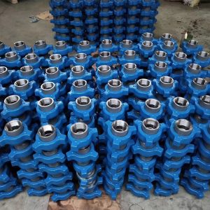
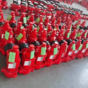
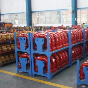
GPE manufactures High-Pressure Rigid Straight Pipe Assemblies, also known as Flow Iron Pup Joints, for hydraulic fracturing, cementing, acidizing, well testing, circulation, pressure-pumping and flowback systems.

A Rigid Straight Pipe Assembly connects two pressure-control components across a defined straight-line distance while maintaining the required bore, working pressure and end-interface geometry. The assembly can be manufactured with Hammer Union, threaded, butt-weld or API flanged ends.

The pressure-containing assembly consists of a high-strength straight pipe section and model-specific end connections. Depending on the configuration, the end connectors are integral, welded, threaded or flanged. GPE controls the pipe material, wall thickness, end transition, weld preparation, heat treatment, machining and pressure testing as one complete pressure system.

The standard manufacturing range covers nominal sizes from 1 to 6 in and rated working pressures from 2,000 to 20,000 psi. Standard and custom lengths are manufactured for pump discharge lines, Frac Manifolds, temporary treatment iron, well-test packages and pressure-control skids.

Available configurations include:

  • Integral Hammer Union Pup Joint
  • Retention-shoulder union-end Pup Joint
  • NPST and approved threaded-end assembly
  • Butt-weld straight pipe assembly
  • Flanged Straight Pipe Assembly
  • Male × Male ends
  • Male × Female ends
  • Female × Female ends
  • Fig 602, Fig 1002, Fig 1502, Fig 2002 and Fig 2202 connections
  • API 6A flanged configurations within the applicable equipment scope
  • Standard Service
  • Low-Temperature Service
  • H₂S and Sour Service
  • Fixed standard lengths
  • Custom end-to-end lengths
  • Replacement-compatible assemblies

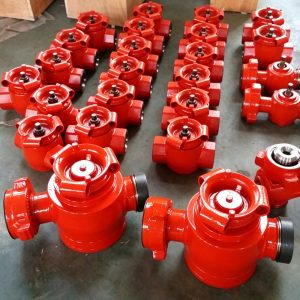
GPE Rigid Straight Pipe Assemblies connect directly with High-Pressure Hammer Unions, High-Pressure Plug Valves, High-Pressure Check Valves, High-Pressure Swivel Joints and Emergency Relief Valves in complete Flowline & Frac Manifold systems.

Need a Straight Pipe Assembly for an Existing Flow Iron System?

Send GPE the nominal size, working pressure, required length, end connections, bore, service class and quantity.

Our engineering team will confirm the correct pipe wall, end-interface geometry, pressure class and dimensional drawing before production.

Request a Straight Pipe Assembly Quote:
https://gpepump.com/contact/

Send Your Flowline Drawing:
info@gpepump.com

Product Short Description

GPE High-Pressure Rigid Straight Pipe Assemblies provide strong, full-bore connections between pumps, valves, manifolds and wellhead equipment.

The assembly combines a high-strength pressure pipe with precisely machined Hammer Union, threaded, butt-weld or flanged ends. The straight flow path reduces unnecessary directional changes and provides lower hydraulic loss than elbows, tees and other directional fittings.

Standard Flow Iron Pup Joints are manufactured in 1–4 in high-pressure configurations, while project-specific rigid straight pipe assemblies extend the range to 6 in. Flanged assemblies are manufactured from 2-1/16 to 7-1/16 in for applicable wellhead, manifold and pressure-control equipment.

Each assembly is manufactured to an approved drawing that defines the bore, wall thickness, end-to-end length, connection type, material class, pressure class, temperature class, service condition and inspection scope.

Product Highlights

  • Nominal sizes from 1 to 6 in
  • Working pressures from 2,000 to 20,000 psi
  • Metric pressure range from 14 to 140 MPa
  • Straight full-flow pressure path
  • Standard and custom lengths
  • Lengths up to 20 ft for standard Pup Joint configurations
  • Integral Hammer Union ends
  • Retention-shoulder union ends
  • NPST and approved threaded ends
  • Butt-weld connections
  • API flanged straight pipe assemblies
  • Male × Male, Male × Female and Female × Female ends
  • Fig 602, Fig 1002, Fig 1502, Fig 2002 and Fig 2202
  • Forged alloy-steel end connections
  • High-strength pressure pipe
  • Controlled pipe wall thickness
  • Smooth internal bore transitions
  • Reduced hydraulic loss
  • Standard, Low-Temperature and H₂S Service
  • PU temperature class from -29°C to 121°C
  • PL temperature class from -46°C to 121°C
  • Material class EE for applicable flanged assemblies
  • Heat-number and serial-number traceability
  • UT, MPI, hardness and dimensional inspection
  • Straightness and wall-thickness inspection
  • Hydrostatic pressure testing
  • Custom dimensions from approved drawings
  • Replacement-compatible manufacturing
  • Complete documentation package

Main Technical Specifications

Parameter GPE Manufacturing Range
Product High-Pressure Rigid Straight Pipe Assembly
Alternative names Pup Joint / Flow Iron Straight Pipe / Straight Pipe Assembly
Product category High-Pressure Flow Iron
Nominal sizes 1–6 in
Working pressure 2,000–20,000 psi
Metric pressure range 14–140 MPa
Pressure series 2K, 3K, 5K, 6K, 10K, 15K and 20K
Standard temperature range -29°C to 121°C
Low-temperature range -46°C to 121°C
Temperature classes PU and PL
Standard lengths 2, 3, 4, 5, 6, 8, 10, 12 and 20 ft
Custom length According to approved drawing
Body construction High-strength pressure pipe with forged end connections
Flow path Straight, full-flow or drawing-controlled bore
End connections Hammer Union, thread, butt weld or API flange
Union options Fig 602, Fig 1002, Fig 1502, Fig 2002 and Fig 2202
End combinations M × M, M × F and F × F
Service environment Standard, Low Temperature or H₂S Service
Main applications Fracturing, cementing, acidizing, testing, circulation and flowback
H₂S material selection NACE MR0175 / ISO 15156
Inspection Material verification, UT, MPI, hardness, dimensional and straightness inspection
Pressure testing Hydrostatic pressure-body and connection-integrity testing
Supply scope Complete pipe assembly, union seals, protectors and documentation

Confirm the Correct Length, Bore and End Connections

The nominal size alone does not define a High-Pressure Straight Pipe Assembly. The final configuration also depends on working pressure, internal bore, pipe wall thickness, end-to-end length, connection figure, male and female orientation, service class, temperature and service fluid.

Send GPE the existing part number, GA drawing, connection schedule or measured dimensions. We will confirm the complete pressure-rated configuration before quotation.

Confirm the Correct Pup Joint Configuration:
https://gpepump.com/contact/

Send Length and Connection Details:
info@gpepump.com

Standard Flow Iron Pup Joint Range

Nominal Size Typical Union Family Typical Working Pressure Standard Length Range
1 in Fig 1502 Up to 15,000 psi 2–12 ft
1-1/2 in Fig 1502 Up to 15,000 psi 2–12 ft
2 in Fig 602 / 1002 / 1502 / 2002 / 2202 6,000–20,000 psi 2–20 ft
3 in Fig 602 / 1002 / 1502 / 2002 / 2202 6,000–20,000 psi 2–20 ft
4 in Fig 602 / 1002 / 1502 6,000–15,000 psi 2–20 ft
5–6 in Engineered connection Project-specific Custom

The approved GPE drawing controls the final bore, pressure class, pipe wall thickness, connection and length.

Flanged Straight Pipe Assembly Range

Parameter GPE Manufacturing Range
Product Flanged Straight Pipe Assembly
Nominal bore 2-1/16 to 7-1/16 in
Working pressure 6,000–20,000 psi
Metric pressure range 42–140 MPa
Material class EE for applicable project requirements
Temperature class PU
Standard temperature range -29°C to 121°C
End configuration Flange × Flange or mixed flange interface
Application Wellhead, manifold, test skid and pressure-control equipment
Manufacturing standard Applicable API Spec 6A requirements when ordered within its scope
Length According to approved GA drawing
Inspection Material, dimensional, NDE and hydrostatic pressure testing

Flange size, type, pressure class, ring groove, bore, material class, PSL and temperature class are defined in the purchase specification.

Product Configurations

Integral Hammer Union Pup Joint

The Integral Pup Joint uses a pressure pipe and integral or permanently attached Hammer Union ends. It provides compact dimensions, defined male and female orientation, rapid Flow Iron makeup and clear pressure-class identification.

Retention-Shoulder Pup Joint

The retention-shoulder design keeps the wing nut secured to the assembly during handling. This reduces loose-component risk and simplifies field rig-up and inventory control.

Threaded Straight Pipe Assembly

Threaded configurations include line-pipe, tubing and approved project threads in Pin × Pin, Pin × Box or Box × Box arrangements.

The exact thread form, taper, pitch, gauge requirement and pressure class are stated on the approved drawing.

NPST Straight Pipe Assembly

NPST configurations use a non-pressure-seal attachment thread for the union sub. The pressure boundary is maintained by the designed shoulder, seal and union structure rather than by the attachment thread alone.

Butt-Weld Straight Pipe Assembly

Butt-weld assemblies connect the pressure pipe directly to forged end fittings, flanges or manifold components.

The drawing defines pipe OD, bore, wall thickness, material, weld bevel, preheat, welding procedure, post-weld heat treatment and NDE requirements.

Flanged Straight Pipe Assembly

The Flanged Straight Pipe Assembly connects fixed wellhead, manifold, test and pressure-control equipment.

Available forms include Flange × Flange, Flange × Hammer Union, Flange × Thread and project-specific crossover assemblies.

Pressure and Connection Families

Fig 602 Straight Pipe Assembly

Fig 602 configurations are used in 6,000 psi cementing, circulation, hot-oil and general well-service systems.

Fig 1002 Straight Pipe Assembly

Fig 1002 configurations are used in 10,000 psi cementing, acidizing, testing and high-pressure well-service lines.

Fig 1502 Straight Pipe Assembly

Fig 1502 is the principal 15,000 psi connection for hydraulic fracturing and high-pressure Flow Iron.

GPE Fig 1502 Pup Joints connect Frac Pumps, Pump Discharge Manifolds, Plug Valves, Check Valves, Swivel Joints, Frac Missiles, Zipper Manifolds and Frac Trees.

Fig 2002 Straight Pipe Assembly

Fig 2002 configurations are manufactured for 20,000 psi pressure-pumping and test systems using qualified high-strength pipe, engineered wall thickness and 20K-rated end connections.

Fig 2202 Sour-Service Assembly

Fig 2202 configurations are used for high-pressure H₂S and sour-service lines with controlled-hardness materials, sour-service seals and NACE MR0175 / ISO 15156 material selection.

Straight Full-Bore Flow Path

The straight internal flow path creates less directional resistance than elbows, tees and cross fittings.

Benefits include:

  • Lower hydraulic loss
  • Reduced local turbulence
  • Lower velocity concentration
  • Improved proppant transport
  • Improved cement-slurry transport
  • Reduced solids accumulation
  • Easier flushing
  • Easier internal inspection

The final pressure loss depends on bore, length, flow rate, density, viscosity and internal surface condition.

Bore and Wall-Thickness Selection

The required bore and wall thickness are controlled by:

  • Nominal size
  • Working pressure
  • Material strength
  • Corrosion allowance
  • Erosion allowance
  • End-connection geometry
  • Pipe length
  • External loading
  • Service temperature
  • H₂S requirements

A larger bore reduces hydraulic loss but also reduces the available wall thickness for a fixed outside diameter. GPE confirms the complete pressure-body design before production.

Standard Lengths and Custom Lengths

Standard lengths include:

  • 2 ft / 610 mm
  • 3 ft / 914 mm
  • 4 ft / 1,219 mm
  • 5 ft / 1,524 mm
  • 6 ft / 1,829 mm
  • 8 ft / 2,438 mm
  • 10 ft / 3,048 mm
  • 12 ft / 3,658 mm
  • 20 ft / 6,096 mm

Custom lengths are manufactured according to manifold spacing, valve envelope, skid layout, handling requirements and transportation limits.

The approved drawing states whether the quoted dimension is measured from male nose, female face, flange face or weld preparation.

Length Tolerance and Straightness

Dimensional control includes:

  • Overall end-to-end length
  • Centerline alignment
  • Pipe straightness
  • End-face perpendicularity
  • Bore concentricity
  • Male and female orientation
  • Flange clocking
  • Weld-end preparation

Length and orientation tolerances are stated on the approved drawing.

Erosion and Wall-Thickness Monitoring

Straight pipes experience lower directional erosion than elbows, but wear still occurs from high fluid velocity, proppant, scale, corrosion, bore mismatch and repeated pressure cycles.

Inspection focuses on:

  • End-connection transitions
  • Weld heat-affected zones
  • Internal bore steps
  • Areas adjacent to valves and fittings
  • Pipe support contact points
  • Previously identified thin-wall locations

UT monitoring intervals are based on pumped volume, service fluid, pressure cycles and field history.

External Loads, Support and Restraint

Rigid Straight Pipe Assemblies are pressure conduits and are not designed to absorb uncontrolled bending or suspended equipment weight.

The installed line requires:

  • Correct pipe supports
  • Level alignment
  • Controlled centerline position
  • No forced union makeup
  • No unsupported valves
  • No excessive torsion
  • No impact loading
  • No use as a lifting point

Misalignment is corrected with suitable High-Pressure Swivel Joints rather than by forcing the pipe into position.

Temporary high-pressure Flow Iron also receives an approved restraint system sized for pipe length, working pressure, connection type and equipment spacing.

Standard, Low-Temperature and H₂S Service

Standard Service

Standard-Service assemblies handle compatible non-sour fluids including fracturing fluid, cement slurry, drilling fluid, completion brine, water, compatible oil-based fluids, well-test fluids and flowback fluids.

Low-Temperature Service

PL-class assemblies use qualified pressure-pipe material, qualified forged ends, controlled heat treatment, impact testing, low-temperature seals and full traceability for service down to -46°C.

H₂S and Sour Service

GPE H₂S Service assemblies use controlled-hardness pressure materials, qualified heat treatment, sour-service end connections, H₂S-compatible seals, hardness inspection and NACE MR0175 / ISO 15156 material selection.

Applications

Hydraulic Fracturing

Rigid Straight Pipe Assemblies connect Frac Pumps, Fluid Ends, Pump Discharge Manifolds, Plug Valves, Check Valves, Swivel Joints, Frac Missiles, Zipper Manifolds and Frac Trees.

Cementing

Pup Joints connect cementing units, high-pressure pumps, cementing manifolds, Plug Valves, cement heads, circulating heads and flush lines.

Acidizing

Acidizing assemblies use pressure materials and seals matched to acid type, concentration, corrosion inhibitor, temperature, H₂S, CO₂ and chloride content.

Well Testing and Flowback

Well-test and flowback assemblies can be exposed to formation sand, residual proppant, scale, completion debris, water, hydrocarbons and corrosive contaminants. Scheduled bore, wall-thickness, weld and connection inspection is required.

Manifold and Skid Integration

GPE manufactures Straight Pipe Assemblies according to the complete equipment layout.

The integration process controls:

  • Pump outlet position
  • Valve spacing
  • Connection orientation
  • Manifold centerlines
  • Flange clocking
  • Pipe support
  • Service access
  • Lifting clearance
  • Restraint attachment
  • Transportation envelope

The assembly can be supplied as part of a complete GPE Flowline & Frac Manifold system.

Replacement-Compatible Manufacturing

GPE manufactures replacement assemblies from existing part numbers, approved drawings, end-to-end dimensions, connection schedules, measured samples and manifold GA drawings.

Replacement verification covers size, pressure, bore, length, connection figure, male and female orientation, flange type, wall thickness, material class, service class and temperature class.

Manufacturing Process

  1. Technical drawing and pressure-boundary review
  2. Pipe and forging material verification
  3. Heat-number assignment
  4. Forged end-connection manufacturing
  5. Rough machining
  6. Controlled heat treatment
  7. Mechanical-property and hardness testing
  8. Pipe cutting and end preparation
  9. Bore and transition machining
  10. Union, thread, weld or flange machining
  11. Qualified welding where applicable
  12. Post-weld heat treatment where specified
  13. Weld NDE
  14. Forging UT and MPI
  15. Dimensional and straightness inspection
  16. Wall-thickness inspection
  17. Connection-gauge inspection
  18. Hydrostatic pressure testing
  19. Permanent product marking
  20. Documentation review and export packaging

Quality Control and Pressure Testing

GPE quality control includes:

  • Raw-material certificate verification
  • Chemical-composition verification
  • Heat-number traceability
  • Pipe material verification
  • Forging UT
  • MPI
  • Weld visual inspection
  • Weld UT or RT where specified
  • Mechanical-property testing
  • Hardness inspection
  • Low-temperature impact testing for PL orders
  • H₂S Service hardness inspection
  • Bore and wall-thickness inspection
  • Overall-length and straightness inspection
  • Connection-gauge inspection
  • Flange and ring-groove inspection
  • Hydrostatic pressure testing

Every complete assembly receives a hydrostatic pressure test according to the approved Inspection and Test Plan.

The test record identifies product model, serial number, nominal size, working pressure, test pressure, medium, stabilization time, hold time, result and test date.

Product Marking and Documentation

Each assembly is permanently marked with:

  • GPE identification
  • Product name
  • Nominal size
  • Working pressure
  • Connection figure
  • End orientation
  • Overall length
  • Standard or H₂S Service
  • PU or PL temperature class
  • Material class where applicable
  • Serial number
  • Pipe and end-sub heat numbers
  • Manufacturing date

The order documentation includes:

  • Certificate of Conformity
  • Product datasheet
  • GA and dimensional drawings
  • Connection schedule
  • Material Test Certificates
  • Heat-treatment records
  • Mechanical-property and hardness reports
  • Low-temperature impact reports where applicable
  • UT, MPI and weld-NDE reports
  • Dimensional and straightness report
  • Wall-thickness report
  • Hydrostatic pressure-test report
  • Serial-number traceability list
  • Installation instructions
  • Packing list

Installation and Routine Inspection

Before installation:

  1. Verify size, pressure and connection figure.
  2. Verify male and female orientation.
  3. Verify overall length.
  4. Inspect all sealing surfaces.
  5. Install the correct union or flange seal.
  6. Align and support the connected equipment.
  7. Install the approved Flow Iron restraint.
  8. Pressure-test the complete line.

Inspect the assembly for corrosion, impact damage, bending, connection leakage, union-thread wear, flange damage, weld cracking, bore erosion, wall-thickness loss, deformation and unreadable markings.

Common Failure Modes

Connection Leakage

Main causes include an incorrect seal, damaged sealing surface, insufficient makeup, mismatched connection figure, external bending load and flange or thread damage.

Bore Erosion

Main causes include high flow velocity, high proppant concentration, internal bore mismatch, abrupt end transition, corrosion and extended pumping duration.

Pipe Bending

Main causes include unsupported equipment weight, forced alignment, vehicle impact, improper handling and thermal movement.

Weld Damage

Main causes include an incorrect welding procedure, external loading, fatigue, impact and corrosion.

Trapped Pressure

Pressure can remain between Check Valves, Plug Valves and closed manifold branches. Both ends are vented and verified at zero pressure before any connection is loosened.

How to Select the Correct Straight Pipe Assembly

  1. Identify the nominal size.
  2. Confirm rated working pressure.
  3. Confirm required internal bore.
  4. Define end-to-end length.
  5. Select Hammer Union, threaded, butt-weld or flanged ends.
  6. Define connection figure.
  7. Define male and female orientation.
  8. Confirm pipe wall thickness.
  9. Select Standard, Low-Temperature or H₂S Service.
  10. State operating temperature.
  11. State service fluid and solids content.
  12. Confirm support and restraint requirements.
  13. Confirm inspection and documentation requirements.

Frequently Asked Questions

What sizes does GPE manufacture?

GPE manufactures Rigid Straight Pipe Assemblies from 1 to 6 in.

What working pressures are available?

The manufacturing range covers 2,000 to 20,000 psi / 14 to 140 MPa.

Is a Rigid Straight Pipe Assembly the same as a Pup Joint?

A Pup Joint is the standard Flow Iron form of a short rigid straight pipe assembly with union ends. The broader Straight Pipe Assembly category also includes threaded, butt-weld and flanged configurations.

What standard lengths are available?

Standard lengths include 2, 3, 4, 5, 6, 8, 10, 12 and 20 ft. Custom lengths are also available.

Which connection is used for 15K fracturing?

Fig 1502 Hammer Union ends are widely used in 15,000 psi fracturing Flow Iron.

Are 20K Pup Joints available?

Yes. GPE manufactures engineered Fig 2002 and other approved 20,000 psi configurations.

Are flanged assemblies available?

Yes. GPE manufactures Flanged Straight Pipe Assemblies from 2-1/16 to 7-1/16 in for applicable wellhead, manifold and pressure-control systems.

What is the difference between integral and NPST designs?

Integral designs use permanently integrated end connections. NPST designs use a non-pressure-seal attachment thread and a separate pressure-sealing structure.

Are M × M, M × F and F × F configurations available?

Yes. GPE manufactures all three arrangements.

Can GPE manufacture H₂S Service assemblies?

Yes. GPE manufactures controlled-hardness sour-service configurations with NACE MR0175 / ISO 15156 material selection.

Can GPE manufacture low-temperature assemblies?

Yes. PL-class assemblies are available for service down to -46°C.

Does API Spec 6A apply to every Straight Pipe Assembly?

No. API Spec 6A applies only when the assembly is ordered within its applicable wellhead, tree and pressure-control equipment scope.

Hammer Union Flow Iron Pup Joints are manufactured to approved GPE drawings, pressure class, service condition and project specifications.

Can the pipe be forced into alignment during makeup?

No. Excessive force creates bending stress and connection misalignment. Correct support, approved dimensions and suitable Swivel Joints are used instead.

Is Flowline restraint required?

Temporary high-pressure Flow Iron is installed with an approved restraint system according to site and operator requirements.

Can GPE manufacture replacement-compatible assemblies?

Yes. GPE manufactures replacement assemblies from drawings, part numbers, dimensions and physical samples.

What inspections are completed?

GPE completes material verification, UT, MPI, hardness, dimensional, straightness, wall-thickness, weld NDE and hydrostatic pressure testing according to the approved configuration.

Request a High-Pressure Straight Pipe Assembly Proposal

GPE manufactures complete Rigid Straight Pipe Assemblies and Pup Joints for Frac Pumps, cementing units, test packages, pressure-control manifolds and high-pressure Flow Iron.

Our manufacturing range includes:

  • 1–6 in nominal sizes
  • 2,000–20,000 psi working pressures
  • Standard and custom lengths
  • Fig 602, Fig 1002 and Fig 1502 ends
  • Fig 2002 and Fig 2202 configurations
  • Integral and retention-shoulder Pup Joints
  • Threaded and butt-weld assemblies
  • Flanged Straight Pipe Assemblies
  • Standard, Low-Temperature and H₂S Service
  • Replacement-compatible dimensions
  • Complete material, NDE and pressure-test documentation

GPE also supplies matching Hammer Unions, Plug Valves, Check Valves, Swivel Joints and Emergency Relief Valves.

Request a Technical Quote:
https://gpepump.com/contact/

Email:
info@gpepump.com

Contact Us Now

Partner with GPE OIL Machinery for your best petroleum mud pump solution.

Contact Us Now