...

High-Pressure Hammer Unions for Fracturing and Flow Iron Connections

High-Pressure Hammer Unions for Fracturing and Flow Iron Connections

Facebook
LinkedIn
Telegram

Description

Product Overview

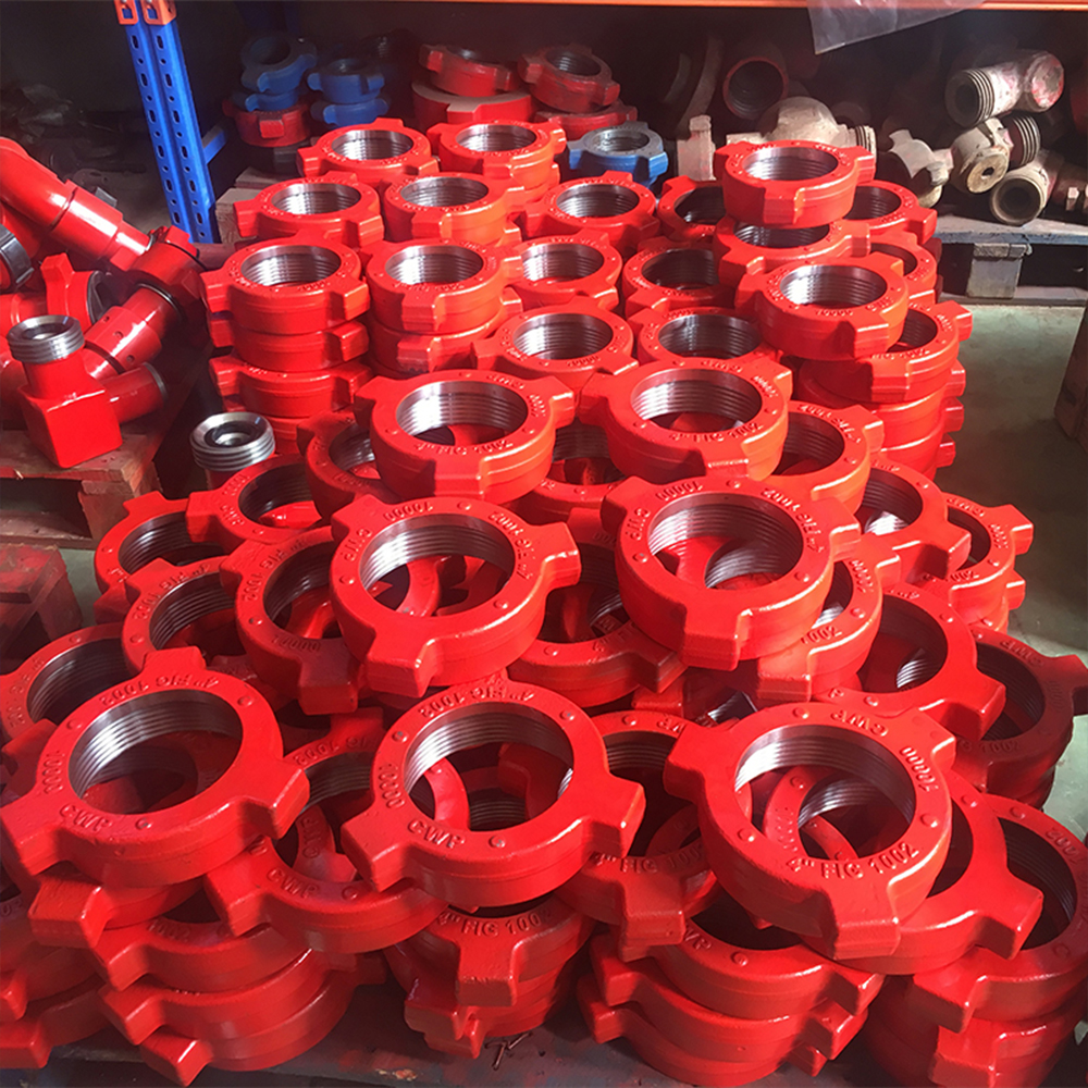
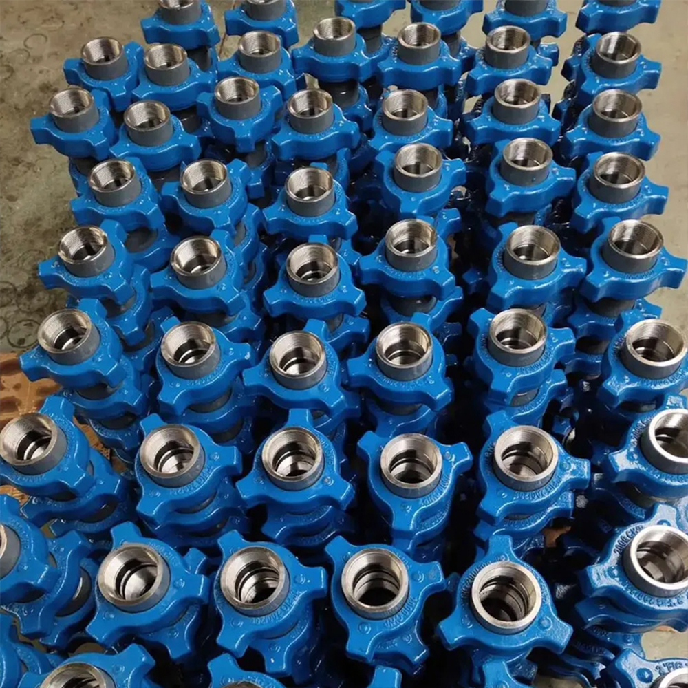
GPE manufactures High-Pressure Hammer Unions for hydraulic fracturing, cementing, acidizing, well testing, circulation, pressure-pumping, drilling and flowback systems.

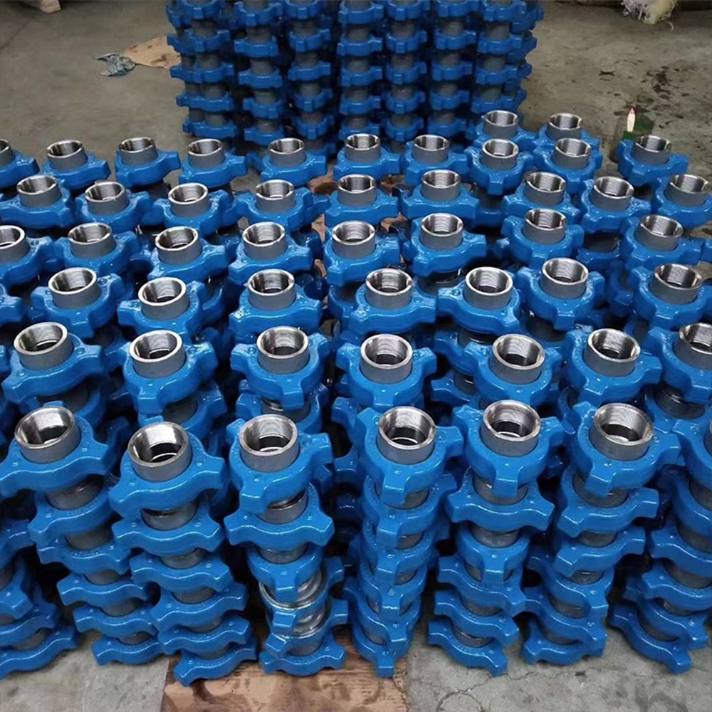
A Hammer Union creates a rapid mechanical connection between two pressure-containing flowline components. The assembly consists of a male sub, female sub, wing nut and figure-specific sealing system. The wing nut uses a heavy-duty ACME thread to draw the two subs together and compress the sealing interface.

The connection can be made up and broken out without rotating the connected pipe. This allows valves, straight pipe assemblies, swivel joints, manifolds and pump discharge lines to be installed, removed or replaced quickly during wellsite rig-up and maintenance.

GPE manufactures Hammer Unions in nominal sizes from 1 to 5 in and pressure classes from 1,000 to 20,000 psi. The product range covers Fig 100, Fig 200, Fig 206, Fig 400, Fig 602, Fig 1002, Fig 1003, Fig 1502, Fig 2002 and Fig 2202 configurations.

Threaded and butt-weld ends are manufactured for Standard Service, Low-Temperature Service and H₂S Service. Complete assemblies, male subs, female subs, wing nuts, seal rings, retaining components, blind unions and repair parts are supplied according to the approved figure, size, pressure class and service condition.

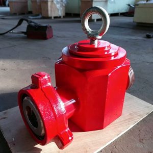
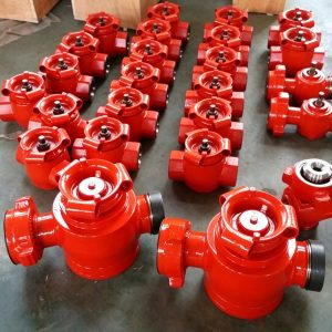
GPE Hammer Unions connect directly with High-Pressure Plug Valves, High-Pressure Check Valves, High-Pressure Swivel Joints and Emergency Relief Valves in complete Flowline & Frac Manifold systems.

Need a Hammer Union for an Existing Flow Iron System?

Send GPE the figure number, nominal size, working pressure, threaded or butt-weld end, Standard or H₂S Service and required quantity.

Our engineering team will confirm the complete matching assembly, connection dimensions, seal structure, pressure class and factory quotation.

Request a Hammer Union Quote:
https://gpepump.com/contact/

Send Your Hammer Union Drawing:
info@gpepump.com

Product Short Description

GPE High-Pressure Hammer Unions provide fast and secure connections between oilfield Flow Iron components.

The forged pressure-containing subs, heavy-duty wing nut, precision-machined ACME thread and figure-specific sealing system withstand pressure pulsation, mechanical vibration, repeated rig-up and demanding well-service conditions.

Low-pressure figures use precision metal-to-metal or O-ring-assisted sealing structures. High-pressure figures use replaceable lip-type seal rings or engineered pressure-supported seal assemblies to maintain reliable sealing and protect the metal seating surfaces.

Each complete union is permanently identified by figure number, nominal size, working pressure and service class to reduce connection mismatch during wellsite assembly.

Product Highlights

  • Nominal sizes from 1 to 5 in
  • Working pressures from 1,000 to 20,000 psi
  • Metric pressure range from 7 to 140 MPa
  • Fig 100, 200, 206, 400, 602, 1002, 1003, 1502, 2002 and 2202
  • Threaded and butt-weld configurations
  • Line-pipe and tubing-thread options
  • Male and female blind unions
  • Standard, Low-Temperature and H₂S Service
  • Forged pressure-containing subs
  • High-strength wing nut
  • Heavy-duty ACME wing-nut thread
  • Quick makeup and breakout
  • Figure-specific metal or elastomer sealing systems
  • Replaceable seal rings
  • Precision-machined seating surfaces
  • Full material heat-number traceability
  • Permanent figure and pressure marking
  • Figure-specific color identification
  • CNC-machined connection dimensions
  • Controlled heat treatment
  • UT, MPI, hardness and thread inspection
  • Figure-specific hydrostatic pressure testing
  • Complete assemblies and spare components
  • Replacement-compatible complete assemblies

Main Technical Specifications

Parameter GPE Manufacturing Range
Product High-Pressure Hammer Union
Alternative names Wing Union / Flow Iron Union
Product category High-Pressure Flow Iron Connection
Nominal sizes 1–5 in
Working pressure 1,000–20,000 psi
Metric pressure range 7–140 MPa
Figure range Fig 100, 200, 206, 400, 602, 1002, 1003, 1502, 2002 and 2202
Main components Male sub, female sub, wing nut and seal system
Nut thread Heavy-duty ACME thread
Pressure-sub material Forged carbon or alloy steel according to figure
Wing-nut material High-strength steel or ductile iron according to figure
Seal structure Metal-to-metal, O-ring, lip-type seal or engineered high-pressure seal
End connections Threaded or butt weld
Thread options Line-pipe, tubing and approved project threads
Service environment Standard, Low Temperature or H₂S Service
Main applications Fracturing, cementing, acidizing, testing, drilling and flowback
Identification Figure, size, pressure, service class and heat traceability
Inspection UT, MPI, hardness, dimensional, thread and seal inspection
Pressure testing Figure-specific hydrostatic pressure test
Supply scope Complete union, subs, nut, seals, blind components and repair parts

Confirm the Correct Figure and Pressure Class

Hammer Unions with different figure numbers, pressure classes, manufacturers or service classes are not treated as interchangeable based only on visual appearance.

Send GPE the figure number, size, connection type, pressure class, service fluid, temperature and existing dimensional information. We will confirm the complete matched assembly and supply the correct seal and spare-parts package.

Confirm the Correct Hammer Union:
https://gpepump.com/contact/

Send Union Specifications:
info@gpepump.com

Hammer Union Figure Selection Guide

Figure Rated Working Pressure Main Sealing Structure End Connection Typical Service
Fig 100 1,000 psi Precision metal-to-metal seat Threaded / Butt Weld Water, oil and low-pressure lines
Fig 200 2,000 psi Precision seating surfaces Threaded General medium-pressure service
Fig 206 2,000 psi O-ring male-sub seal Threaded Manifolds and service piping
Fig 400 4,000 psi Ball-and-cone metal seal Threaded / Butt Weld Medium-pressure water, oil and gas
Fig 602 6,000 psi Replaceable resilient seal ring Threaded / Butt Weld Cementing, circulation and hot-oil service
Fig 1002 10,000 psi Replaceable lip-type seal ring Threaded / Butt Weld High-pressure cementing, acidizing and testing
Fig 1003 10,000 psi for 3 in; 7,500 psi for 4–5 in butt-weld sizes Misaligning ball-seat and seal ring Butt Weld High-pressure piping requiring angular alignment
Fig 1502 15,000 psi High-pressure replaceable seal ring Threaded / Butt Weld Hydraulic fracturing and high-pressure Flow Iron
Fig 2002 20,000 psi Ultra-high-pressure engineered seal Butt Weld / Integral interface Ultra-high-pressure pumping and testing
Fig 2202 15,000 psi sour-service configuration Sour-service high-pressure seal assembly Butt Weld H₂S pressure-control and well-service lines

The approved GPE drawing and product nameplate control the final size, pressure rating, material, seal package and end preparation. A butt-weld assembly is also limited by the wall thickness, material and pressure rating of the connected pipe.

Figure-Specific Product Range

Figure 100 Hammer Union

Fig 100 is an economical 1,000 psi union for water, oil and compatible gas service. The precision metal-to-metal seating surfaces create the pressure seal without a replaceable primary seal ring.

Figure 200 Hammer Union

Fig 200 is a general-purpose 2,000 psi threaded union for medium-pressure service. The precision seating surfaces create the seal as the wing nut draws the subs together.

Figure 206 Hammer Union

Fig 206 uses an O-ring installed on the male sub. The replaceable elastomer creates the primary seal and supports rapid maintenance.

Figure 400 Hammer Union

Fig 400 uses a precision ball-and-cone metal sealing structure for 4,000 psi water, oil and compatible gas lines.

Figure 602 Hammer Union

Fig 602 uses a replaceable resilient seal ring in the female sub. It is used for 6,000 psi cementing, circulation, hot-oil and well-service systems.

Figure 1002 Hammer Union

Fig 1002 is used for 10,000 psi cementing, acidizing, well testing and pressure-pumping lines. The replaceable lip-type seal ring creates the pressure barrier and protects the metal seating surfaces.

Figure 1003 Misaligning Hammer Union

Fig 1003 is a butt-weld misaligning union for piping that requires controlled angular correction. The ball-seat geometry allows up to 7.5 degrees from the centerline, providing 15 degrees of total alignment range.

Figure 1502 Hammer Union

Fig 1502 is the principal 15,000 psi connection for hydraulic fracturing and high-pressure Flow Iron. It is used throughout GPE Swivel Joints, Plug Valves and Check Valves.

Figure 2002 Hammer Union

Fig 2002 is manufactured for 20,000 psi Flow Iron, pressure-pumping and test systems. The complete 20K assembly uses qualified pressure materials, controlled wall thickness and an engineered seal package.

Figure 2202 Hammer Union

Fig 2202 is manufactured for 15,000 psi H₂S and sour-service applications. The body materials, hardness, heat treatment, seals and retaining components are controlled for the stated sour environment.

Hammer Union Components

Male Sub

The male sub enters the female sub and forms one side of the pressure-sealing interface. It contains the male sealing nose, flow bore, external connection and nut-retaining geometry.

Female Sub

The female sub receives the male sub and contains the metal seat or seal-ring groove. The female sub also carries the external ACME thread engaged by the wing nut.

Wing Nut

The wing nut draws the male and female subs together. The lugs provide the impact surfaces used during makeup and breakout.

A nut is removed from service when the lugs are flattened, mushroomed, cracked or severely worn.

Seal Ring

The seal ring provides the primary pressure barrier in figure designs that use an elastomeric seal.

Seal selection is controlled by:

  • Figure number
  • Nominal size
  • Service fluid
  • Temperature
  • H₂S exposure
  • Chemical compatibility
  • Explosive-decompression requirement

ACME Wing-Nut Thread

The coarse ACME thread provides high axial clamping force, rapid makeup, large thread contact area and repeated assembly capability.

Thread quality is controlled through CNC machining, dimensional inspection and figure-specific gauges.

The thread is cleaned and inspected before makeup. A damaged thread is not forced into engagement.

Metal and Elastomer Sealing Systems

Low- and medium-pressure figures use precision metal seating or O-ring-assisted sealing.

High-pressure figures use replaceable lip-type or pressure-supported seals.

The seal is replaced when it is cut, extruded, hardened, swollen, chemically attacked or permanently deformed.

Threaded Hammer Unions

GPE manufactures line-pipe, tubing and approved project-thread connections.

The drawing states the exact thread type, nominal size, pin or box orientation, gauge requirement and pressure class.

API line-pipe threads are inspected with calibrated gauges where specified. Thread conformity does not by itself certify the complete Hammer Union to a separate API product specification.

Butt-Weld Hammer Unions

Butt-weld unions are welded into pup joints, rigid pipe, manifolds and equipment assemblies.

The approved drawing defines:

  • Pipe OD
  • Bore
  • Wall thickness
  • Pipe schedule
  • Weld bevel
  • Root face
  • Material grade
  • NDE requirements
  • Final pressure rating

The pressure rating is limited by the lowest-rated union component, connected pipe and completed weld.

Standard Service

Standard-Service Hammer Unions handle compatible non-sour fluids including water, fracturing fluid, cement slurry, drilling fluid, completion brine, compatible oil-based fluids, well-test fluids and flowback fluids.

H₂S and Sour Service

GPE H₂S Service Hammer Unions use controlled-hardness pressure materials, qualified heat treatment, sour-service seals, hardness inspection and NACE MR0175 / ISO 15156 material selection.

Standard-Service and H₂S Service components are not mixed.

Color Identification and Marking

Figure-specific colors provide a rapid visual identification aid, but color is not the only verification method.

Each complete union is marked with:

  • Figure number
  • Nominal size
  • Working pressure
  • Standard or H₂S Service
  • Material heat number
  • Product or batch traceability
  • Manufacturing date

Connection Compatibility

A safe connection requires a matched male sub, female sub, wing nut and seal system.

The following items must match:

  • Figure number
  • Nominal size
  • Pressure class
  • Male and female geometry
  • ACME thread
  • Seal profile
  • Bore
  • Service class
  • Temperature class

GPE supplies replacement-compatible complete assemblies according to approved interface drawings.

Components from different manufacturers are not mixed unless the complete connection has been formally verified, approved and pressure tested as one assembly.

Visual similarity is not proof of compatibility.

Applications

Hydraulic Fracturing

Hammer Unions connect Frac Pumps, discharge manifolds, Plug Valves, Check Valves, Swivel Joints, straight pipe assemblies, Frac Missiles, Zipper Manifolds and Frac Trees.

Cementing

Fig 602, Fig 1002 and Fig 1502 unions connect cementing units, pumps, manifolds, cement heads, circulating heads and flush lines.

Acidizing

Acidizing unions use materials and seals matched to acid type, concentration, corrosion inhibitor, temperature, H₂S, CO₂ and chloride content.

Well Testing and Flowback

Temporary high-pressure test and flowback lines use Hammer Unions for rapid rig-up. These assemblies receive scheduled bore, thread, seal and wall-thickness inspection.

Manufacturing Process

  1. Figure-specific material selection
  2. Raw-material certificate verification
  3. Heat-number identification
  4. Forging or approved nut manufacturing
  5. Forging ultrasonic inspection
  6. Rough machining
  7. Controlled heat treatment
  8. Mechanical-property and hardness testing
  9. Internal-bore machining
  10. Male- and female-seat machining
  11. ACME thread machining
  12. Seal-groove machining
  13. Threaded-end or butt-weld preparation
  14. Magnetic-particle inspection
  15. Dimensional and thread-gauge inspection
  16. Component matching
  17. Permanent figure and pressure marking
  18. Hydrostatic pressure testing
  19. Final inspection
  20. End protection and export packaging

Quality Control and Testing

GPE quality control includes:

  • Material certificate review
  • Chemical-composition verification
  • Heat-number traceability
  • Heat-treatment monitoring
  • Mechanical-property testing
  • Low-temperature impact testing for specified orders
  • Hardness inspection
  • Forging UT
  • MPI
  • Internal-bore and wall-thickness inspection
  • Metal-seat and seal-groove inspection
  • ACME thread inspection
  • End-thread gauge inspection
  • Butt-weld preparation inspection
  • Component matching inspection
  • Hydrostatic pressure testing

The pressure-test record identifies figure number, size, working pressure, test pressure, medium, hold time, traceability and acceptance result.

Installation and Critical Safety

Before makeup:

  1. Verify figure number, size, pressure and service class.
  2. Inspect the male and female subs.
  3. Inspect the wing-nut thread and lugs.
  4. Install the correct clean seal.
  5. Align and support the connected piping.
  6. Engage the nut by hand.
  7. Complete makeup using the approved striking procedure.
  8. Verify full engagement.
  9. Pressure-test the completed line according to site procedure.

Critical requirements:

  • Never strike, tighten or loosen a pressurized union.
  • Never exceed the marked working pressure.
  • Never mix figure numbers.
  • Never mix Standard and H₂S Service components.
  • Never use a damaged wing nut.
  • Never force mismatched threads.
  • Never use the union as a lifting or suspension point.
  • Never assume color alone confirms compatibility.
  • Never reuse a damaged seal.
  • Never install an unmarked component in high-pressure service.

Inspection and Rejection

Inspect the union for lug deformation, ACME thread wear, cracks, corrosion, erosion, seal damage, metal-seat scoring, bore washout, marking damage and service-class mismatch.

Remove the union from service when inspection identifies:

  • Cracked pressure parts
  • Flattened or mushroomed lugs
  • Stripped or deformed threads
  • Deep seal-surface damage
  • Unacceptable bore erosion
  • Permanent deformation
  • Unreadable pressure marking
  • Incorrect service components
  • Leakage during testing
  • Unverified compatibility

Spare Parts

GPE supplies:

  • Complete assemblies
  • Male subs
  • Female subs
  • Wing nuts
  • Seal rings
  • O-rings
  • Lip seals
  • Retaining rings
  • Blind plugs
  • Blind caps
  • Thread protectors
  • Butt-weld subs
  • Seal kits
  • Complete replacement packages

Common Failure Modes

Connection Leakage

Main causes include an incorrect seal, damaged groove, insufficient makeup, mismatched components, pressure-class mismatch, bore erosion and chemical incompatibility.

Difficult Makeup

Main causes include dirty threads, nut deformation, cross-threading, pipe misalignment, mismatched figure components and excessive external load.

Nut Lug Deformation

Main causes include excessive striking, repeated impact damage, corrosion and attempted breakout under pressure.

Seal Extrusion

Main causes include an incorrect seal profile, excessive pressure, damaged support geometry, chemical swelling and excessive temperature.

Thread Failure

Main causes include cross-threading, forced makeup, severe wear, corrosion and insufficient engagement.

Every affected assembly is isolated, depressurized, inspected, repaired with approved components and pressure tested before reuse.

Why Buyers Select GPE Hammer Unions

Pressure-Pumping Companies

GPE provides 1K–20K connections, Fig 602–2002 high-pressure configurations, Standard and H₂S Service, complete matched assemblies and long-term seal support.

Flow Iron Rental and Repair Companies

GPE provides figure-specific components, seal packages, dimensional drawings, inspection support, batch traceability, blind unions and replacement-compatible complete assemblies.

Equipment Manufacturers

GPE provides threaded and butt-weld interface drawings, male/female orientation, manifold integration, inspection plans, witnessed testing and complete documentation.

How to Select the Correct Hammer Union

  1. Identify the figure number.
  2. Confirm nominal size.
  3. Confirm working pressure.
  4. Select threaded or butt-weld construction.
  5. Define thread type or pipe schedule.
  6. Define male, female or blind configuration.
  7. Select Standard, Low-Temperature or H₂S Service.
  8. State the temperature range.
  9. State the service fluid.
  10. Confirm dimensional compatibility.
  11. Confirm seal material.
  12. Confirm test and documentation requirements.
  13. Confirm spare seal and component quantities.

Frequently Asked Questions

What sizes does GPE manufacture?

GPE manufactures Hammer Unions from 1 to 5 in.

What pressure classes are available?

The manufacturing range covers 1,000 to 20,000 psi / 7 to 140 MPa.

Which figures are available?

GPE manufactures Fig 100, 200, 206, 400, 602, 1002, 1003, 1502, 2002 and 2202.

Which figure is used for 15K fracturing?

Fig 1502 is the principal 15,000 psi connection used in hydraulic fracturing Flow Iron.

Which figure is used for 10K service?

Fig 1002 is used for 10,000 psi cementing, acidizing, testing and well-service lines.

What is Fig 1003?

Fig 1003 is a misaligning butt-weld union that provides controlled angular correction for high-pressure pipework.

Which figure is used for 20K service?

Fig 2002 is used in engineered 20,000 psi Flow Iron and pressure-pumping systems.

Which figure is used for H₂S Service?

Fig 2202 is used for 15K sour-service applications. GPE also manufactures other figure configurations with controlled-hardness materials and NACE MR0175 / ISO 15156 material selection.

Are threaded and butt-weld unions available?

Yes. GPE manufactures both configurations according to the approved thread or weld-preparation drawing.

Can different figure numbers be connected?

No. Different figures are not mixed.

Can GPE parts be mixed with another manufacturer’s components?

GPE supplies replacement-compatible complete assemblies. Individual components from different manufacturers are not mixed unless the complete combination has been formally verified and pressure tested.

Is color enough to identify a union?

No. Verify the permanent figure, size, pressure and service markings. Color is only a visual aid.

Can a union be tightened under pressure?

No. A pressurized union is never struck, tightened, loosened or dismantled.

Can the union support suspended pipe?

No. Hammer Unions are pressure connections, not suspension or lifting devices.

What is the difference between Standard and H₂S Service?

H₂S Service uses controlled-hardness materials, qualified heat treatment, sour-service seals, hardness inspection and NACE MR0175 / ISO 15156 material selection.

Does API Spec 16C apply to every Hammer Union?

No. Hammer Unions are manufactured to the approved figure drawing, pressure class, service condition and purchase specification.

Are seals available separately?

Yes. GPE supplies figure-specific O-rings, lip seals, pressure seals and complete seal kits.

Can GPE manufacture replacement-compatible unions?

Yes. GPE manufactures complete replacement assemblies from approved drawings, dimensions, part numbers and physical samples.

What testing is completed?

GPE completes material inspection, dimensional inspection, thread inspection, NDE and figure-specific hydrostatic pressure testing.

Request a High-Pressure Hammer Union Proposal

GPE manufactures complete Hammer Union connections and replacement components for fracturing, cementing, acidizing, well testing, drilling, pressure-pumping and flowback systems.

Our manufacturing range includes:

  • 1–5 in nominal sizes
  • 1,000–20,000 psi working pressures
  • Fig 100 through Fig 2202 configurations
  • Threaded and butt-weld ends
  • Male, female and blind components
  • Standard, Low-Temperature and H₂S Service
  • Metal-to-metal and replaceable seal structures
  • Replacement-compatible complete assemblies
  • Complete material and pressure-test documentation
  • Seal rings, wing nuts, subs and spare-parts kits

GPE also supplies complete pressure-control assemblies with Plug Valves, Check Valves, Swivel Joints and Emergency Relief Valves.

Request a Technical Quote:
https://gpepump.com/contact/

Email:
info@gpepump.com

Contact Us Now

Partner with GPE OIL Machinery for your best petroleum mud pump solution.

Contact Us Now