

Description
Product Overview
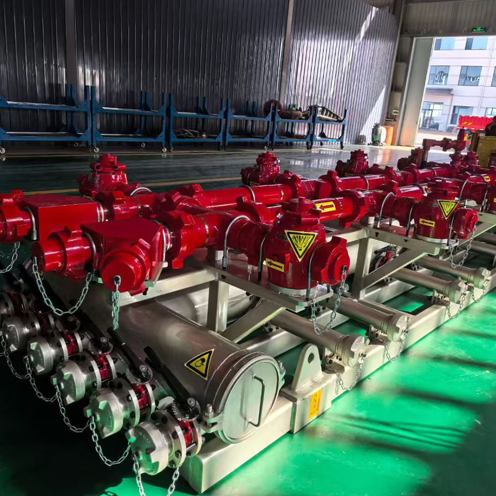
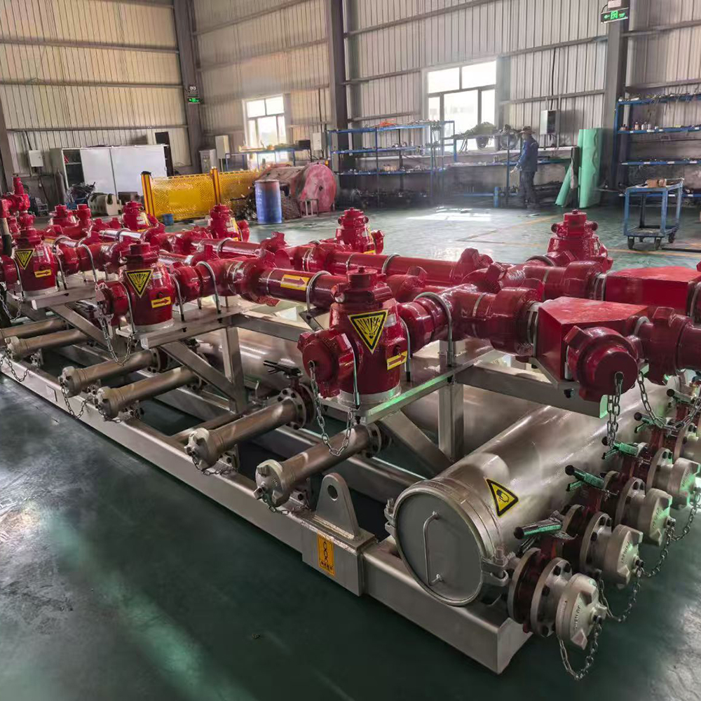
GPE manufactures High-Low Pressure Combined Manifold Skids for multi-pump hydraulic fracturing, acidizing, pressure-testing and high-rate well-stimulation operations.
The complete skid integrates low-pressure fluid gathering, pump-suction distribution, high-pressure discharge collection, branch isolation, pressure monitoring, pipe support, transport structure and maintenance access on one modular base.
During fracturing operations, the low-pressure manifold receives treatment fluid from blending, hydration or storage equipment and distributes it to multiple Frac Pumps. The high-pressure manifold collects the discharge from the connected pumps and transfers the combined flow toward the diverter manifold, zipper manifold, Frac Tree or wellhead system.
GPE manufactures two primary high-pressure architectures:
- Conventional 2–3 in Flow Iron branch manifold with multiple pump connections
- Large-bore central manifold with 5-1/8 or 7-1/16 in main bore and 3 in high-pressure side branches
The high-pressure system is manufactured for 6,000–20,000 psi service. The low-pressure gathering system uses 8–12 in headers, with standard 1 MPa / 145 psi configurations and project-specific pressure classes.
The complete manifold is engineered according to the number of connected pumps, target total flow rate, operating pressure, fluid system, proppant loading, available site footprint, transportation limits and required operating philosophy.
GPE integrates the skid with High-Pressure Plug Valves, High-Pressure Check Valves, High-Pressure Swivel Joints, Emergency Relief Valves, Hammer Unions, Integral Fittings and Rigid Straight Pipe Assemblies as one complete Flowline & Frac Manifold system.
Need a Manifold Skid for Multiple Frac Pumps?
Send GPE the number of connected pumps, pump outlet size, maximum combined flow rate, high-pressure rating, low-pressure header size, branch connection, skid footprint and service environment.
Our engineering team will prepare the manifold flow diagram, port schedule, skid arrangement and factory quotation.
Request a Frac Manifold Skid Quote:
https://gpepump.com/contact/
Send Your Frac Spread Layout:
info@gpepump.com
Product Short Description
GPE High-Low Pressure Combined Manifold Skids centralize low-pressure fluid distribution and high-pressure pump-discharge collection for multi-pump fracturing operations.
The low-pressure section distributes fluid from the blender or supply source to individual Frac Pumps through an 8–12 in gathering header. The high-pressure section collects pump output through 2–3 in branch connections and transfers the combined flow through a conventional Flow Iron manifold or a large-bore 5-1/8 or 7-1/16 in trunk.
The skid structure provides defined support, transport, lifting, drainage, valve access and service clearance. Modular branch layouts allow the system to match the required pump quantity, treatment rate and wellsite arrangement.
High-pressure components are manufactured from forged alloy steel and pressure-tested individually and as an assembled manifold system. Standard, low-temperature and H₂S Service configurations are supplied with complete material, NDE, pressure-test and FAT documentation.
Product Highlights
- Integrated high- and low-pressure manifold skid
- Designed for multi-pump fracturing operations
- High-pressure working range from 6,000 to 20,000 psi
- Standard low-pressure manifold rating of 1 MPa / 145 psi
- 2–3 in high-pressure pump branches
- 8–12 in low-pressure gathering header
- Optional 5-1/8 and 7-1/16 in large-bore high-pressure trunk
- Fig 1502 and Fig 2002 high-pressure branch connections
- Fig 206 and Fig 207 low-pressure connections
- Modular pump-branch quantity
- Custom inlet, outlet and branch orientation
- Compact integrated skid structure
- Reduced field connection count
- Faster wellsite rig-up and pad-to-pad relocation
- Lower hydraulic resistance through streamlined routing
- Long-Sweep and large-bore flow-path options
- Manual or hydraulically actuated valves
- Local and remote position indication
- Pressure gauges and transmitter interfaces
- Emergency shutdown integration
- Standard, Low-Temperature and H₂S Service
- PU and PL temperature classes
- NACE MR0175 / ISO 15156 material selection
- Separate HP and LP hydrostatic testing
- Complete skid FAT
- Custom transport dimensions
- Complete spare-parts and redress packages
Main Technical Specifications
| Parameter | GPE Manufacturing Range |
|---|---|
| Product | High-Low Pressure Combined Manifold Skid |
| Alternative names | Frac Manifold Skid / High-Low Pressure Fracturing Manifold |
| Primary function | Low-pressure fluid distribution and high-pressure discharge collection |
| High-pressure working range | 6,000–20,000 psi |
| Metric high-pressure range | 42–140 MPa |
| Standard high-pressure classes | 6K, 10K, 15K and 20K |
| Conventional HP branch size | 2–3 in |
| Large-bore HP main bore | 5-1/8 or 7-1/16 in |
| HP side branch connections | 3 in Fig 1502, Fig 2002 or approved project interface |
| Low-pressure header size | 8–12 in |
| Standard LP working pressure | 1 MPa / 145 psi |
| LP connection options | Fig 206, Fig 207, flange or approved project connection |
| Operating temperature | -29°C to 121°C |
| Low-temperature range | -46°C to 121°C |
| Temperature classes | PU and PL |
| Service environment | Standard, Low Temperature or H₂S Service |
| High-pressure valves | Plug Valve, Check Valve and project-specific isolation valves |
| Low-pressure valves | Butterfly Valve and project-specific control valves |
| HP flow components | Integral fittings, rigid straight pipe, swivel joints and Hammer Unions |
| Manifold layout | Single-sided, double-sided or project-specific modular layout |
| Actuation | Manual, hydraulic or integrated remote control |
| Instrumentation | Pressure gauge, transmitter and sensor interfaces |
| Skid structure | Welded structural-steel base with lifting and tie-down points |
| Main applications | Fracturing, acidizing, high-rate pressure pumping and testing |
| H₂S material selection | NACE MR0175 / ISO 15156 |
| Testing | HP hydrotest, LP hydrotest, valve function test and FAT |
| Supply scope | Complete assembled skid, controls, instruments and documentation |
Confirm the Pump Count, Flow Rate and Manifold Architecture
The correct manifold configuration is controlled by the total pump output and complete Frac Spread layout.
GPE engineering reviews the number of connected pumps, pump outlet size, maximum rate per branch, total treatment rate, normal and maximum pressure, central trunk bore, proppant concentration, downstream interface, skid footprint and control philosophy.
Confirm the Correct Manifold Configuration:
https://gpepump.com/contact/
Send Pump and Flow Requirements:
info@gpepump.com
Functional Process
Low-Pressure Fluid Distribution
Treatment fluid enters the low-pressure gathering header from the blender, hydration unit, storage system or transfer pump.
The low-pressure section:
- Receives mixed treatment fluid
- Divides flow between connected Frac Pumps
- Isolates individual low-pressure branches
- Provides drainage and flushing points
- Supports hose or rigid-pipe pump connections
- Reduces suction-side flow imbalance
The header size and branch layout are selected to maintain stable pump supply and control suction-system pressure loss.
High-Pressure Pump Collection
Each Frac Pump discharges through a dedicated high-pressure branch containing the required Check Valve, Plug Valve, rigid pipe, swivel joint and connection fittings.
The high-pressure section:
- Receives output from multiple pumps
- Prevents reverse flow into stopped pump branches
- Isolates individual pumps
- Combines branch flow
- Transfers the total treatment rate toward the wellhead
- Provides pressure-monitoring points
- Supports controlled shutdown and maintenance isolation
Combined Wellhead Delivery
The collected high-pressure fluid exits through the main manifold outlet and continues to the diverter manifold, zipper manifold, Frac Tree or wellhead connection.
Conventional Flow Iron Manifold
The conventional manifold uses multiple 2–3 in high-pressure Flow Iron branches connected through tees, crosses, Plug Valves, Check Valves, rigid pipe and union connections.
Advantages include:
- Proven field configuration
- Modular branch replacement
- Familiar service procedures
- Wide spare-parts availability
- Flexible pump quantity
- Easy reconfiguration
- Compatibility with Fig 1502 and Fig 2002 equipment
Large-Bore High-Pressure Manifold
The large-bore manifold uses a 5-1/8 or 7-1/16 in central high-pressure trunk with multiple 3 in side branches.
Advantages include:
- Higher combined flow capacity
- Lower hydraulic resistance
- Reduced high-pressure connection count
- Fewer potential leak points
- Simplified main flow route
- Compact high-rate system architecture
- Improved continuous-pumping capability
Low-Pressure Gathering Manifold
The low-pressure manifold uses an 8–12 in main header with multiple pump-suction branches.
Typical components include:
- Large-bore inlet header
- Butterfly Valves
- Branch outlets
- Flexible hose or rigid-pipe interfaces
- Drain and flush connections
- Pressure or vacuum monitoring points
- Supports and vibration isolation
- Fig 206, Fig 207 or flanged connections
High-Pressure Branch Assembly
Each pump branch is configured with:
- Pump outlet connection
- Rigid Straight Pipe Assembly
- High-Pressure Check Valve
- High-Pressure Plug Valve
- High-Pressure Swivel Joint
- Hammer Union
- Integral Fittings
- Pressure-monitoring interface
- Flowline restraint attachment
The Check Valve prevents manifold pressure from returning into a stopped pump. The Plug Valve provides controlled branch isolation.
Main Discharge Assembly
Available main discharge interfaces include:
- Fig 1502 Flow Iron outlet
- Fig 2002 high-pressure outlet
- 5-1/8 in flanged or hub outlet
- 7-1/16 in flanged or hub outlet
- Custom crossover connection
- Dual or redundant discharge paths
Single-Sided and Double-Sided Layouts
A single-sided layout creates one defined operating side and simplifies vehicle approach. A double-sided layout increases connection density, shortens branch routing and reduces total skid length.
The final arrangement follows the Frac Spread equipment plan, traffic-control requirements and maintenance-access requirements.
Modular Skid Design
The manifold is divided into transportable and serviceable modules.
Modular construction provides:
- Factory-controlled assembly
- Faster site installation
- Reduced field welding
- Defined lifting points
- Simplified transportation
- Easier component replacement
- Scalable pump-branch quantity
- Faster pad-to-pad relocation
Reduced Connection Count
GPE reduces unnecessary connection count through integrated manifold blocks, large-bore central trunks, custom-length rigid pipe, integral fittings, optimized valve spacing and direct branch routing.
Reducing connections improves rig-up speed, inspection efficiency and pressure-system reliability.
Streamlined Flow Path and Erosion Control
Flow-path design includes:
- Large-bore central routing
- Long-Sweep transitions
- Gradual reducers
- Angled branch entries
- Matched internal bores
- Reduced internal steps
- Controlled tee and cross geometry
The highest erosion exposure occurs opposite branch entries, at elbow outer radii, downstream of reducers, at bore mismatches and in partially open valves.
GPE controls erosion through forged alloy-steel components, Long-Sweep fittings, matched bores, replaceable valve internals and defined UT inspection locations.
Valve, Instrument and ESD Integration
High-pressure Plug Valves provide branch isolation. Check Valves prevent reverse pressure into stopped pumps. Emergency Relief Valves protect selected pump or manifold sections from pressure above the calibrated setting.
The manifold can include:
- Manual or hydraulic Plug Valves
- Check Valves on pump branches
- Local pressure gauges
- Pressure transmitters
- Valve-position switches
- Temperature transmitters
- Data-acquisition junction box
- Remote HMI interface
- ESD signal interface
- Local manual override
Skid Structure
The structural-steel base includes:
- Equipment and pipe supports
- Valve supports
- Lifting points
- Tie-down points
- Handling provisions
- Drainage channels
- Access platforms where required
- Transport locking points
- Identification plates
The structural design is based on operating weight, transport load, lifting load, piping reaction and site conditions.
Standard, Low-Temperature and H₂S Service
Standard-Service manifolds handle compatible non-sour fracturing, acidizing, testing and flowback fluids.
PL-class configurations use qualified materials, low-temperature seals and impact-tested pressure components for service down to -46°C.
H₂S Service systems use controlled-hardness materials, qualified heat treatment, sour-service seals, full traceability and NACE MR0175 / ISO 15156 material selection.
Standards Positioning
The complete manifold skid is manufactured according to:
- Approved GPE system drawings
- Project design basis
- Component pressure classes
- Customer purchase specification
- Inspection and Test Plan
- Functional and pressure-test procedures
API Spec 6A requirements are applied only to applicable flanged, hub, wellhead and tree components supplied within that standard’s defined scope.
Hammer Union Flow Iron components are manufactured to approved figure drawings, pressure classes, service conditions and project requirements.
Manufacturing Process
- Process-design and flow-diagram review
- Pump and interface data confirmation
- Manifold hydraulic-layout review
- Skid GA and port-schedule preparation
- Pressure-boundary drawing approval
- Raw-material verification
- Forging and pipe-component manufacturing
- Heat treatment and mechanical testing
- CNC machining
- Structural-skid fabrication
- Qualified welding and weld NDE
- Pressure-component UT and MPI
- Valve and Flow Iron assembly
- Low-pressure piping assembly
- Instrument and control installation
- Dimensional and alignment inspection
- HP hydrostatic testing
- LP hydrostatic testing
- Valve functional testing
- Control and ESD testing
- Complete FAT
- Preservation and export packing
Quality Control and Testing
GPE quality control includes:
- Material certificate verification
- Chemical-composition verification
- Heat-number traceability
- Heat-treatment records
- Mechanical-property testing
- Hardness and low-temperature impact testing
- H₂S Service hardness control
- Forging UT and MPI
- Weld visual and specified NDE
- Bore and wall-thickness inspection
- Valve and connection inspection
- Skid dimensional inspection
- Port-orientation inspection
- Instrument calibration
- HP hydrostatic test
- LP hydrostatic test
- Functional and ESD test
- Final FAT
The high- and low-pressure sections are tested independently. The FAT verifies drawing compliance, connection orientation, valve operation, position feedback, instrument calibration, ESD logic, drains, vents, lifting points and documentation.
Product Documentation
The project documentation includes:
- Certificate of Conformity
- General arrangement drawing
- Process flow diagram
- Piping and Instrumentation Diagram
- Port and connection schedule
- Valve and instrument lists
- Material Test Certificates
- Heat-treatment and mechanical-property reports
- Hardness and impact-test reports
- UT, MPI and weld NDE reports
- Dimensional-inspection report
- HP and LP hydrostatic-test reports
- Valve functional-test report
- Instrument calibration certificates
- FAT report
- Lifting drawing
- Installation manual
- Operation and maintenance manual
- Spare-parts list
- Packing list
Site Installation and Operation
Site installation includes positioning and leveling the skid, securing transport modules, connecting LP supply and pump-suction lines, connecting HP pump branches and the main discharge, installing Flow Iron restraints, connecting controls and completing site pressure tests.
Before pumping, operators verify pressure ratings, service compatibility, Check Valve direction, Plug Valve position, relief protection, LP supply, HP outlet alignment, restraints, instruments and ESD function.
During pumping, monitor HP and LP pressures, valve positions, leakage, vibration, temperature and branch pressure balance.
Maintenance
Routine maintenance includes:
- Cleaning the skid
- Inspecting union, flange and hub connections
- Inspecting Plug Valve operating torque
- Inspecting Check Valve internals
- Inspecting swivel-joint seals and bearings
- Measuring pipe and fitting wall thickness
- Inspecting LP Butterfly Valves
- Inspecting structural supports
- Inspecting lifting and tie-down points
- Calibrating pressure instruments
- Testing ESD functions
- Replacing worn seals and redress components
- Hydrotesting repaired pressure sections
Common Failure Modes
Uneven Pump Suction
Main causes include an undersized LP header, restricted branch, partially closed valve, hose collapse, poor distribution or excessive suction-line length.
High HP Manifold Pressure Loss
Main causes include an undersized central flow path, excessive fittings, bore mismatch, partially open Plug Valve, high solids loading or internal wear.
Reverse Pressure Into a Pump Branch
Main causes include Check Valve damage, seat contamination, incorrect flow direction or worn flapper and dart components.
High-Pressure Leakage
Main causes include damaged union seals, incorrect connection figures, insufficient makeup, valve seal failure, erosion or external pipe load.
Excessive Vibration
Main causes include unsupported piping, pump pulsation, loose skid anchors, incorrect support spacing, misalignment or damaged restraints.
Each affected section is shut down, isolated, depressurized, inspected, repaired and pressure-tested before return to service.
How to Select the Correct Manifold Skid
- Confirm the number and model of Frac Pumps.
- Confirm the maximum pump rate per unit.
- Confirm the maximum combined treatment rate.
- Confirm normal and maximum pressure.
- Select conventional or large-bore HP architecture.
- Confirm HP branch size and connection.
- Confirm LP header and branch sizes.
- Confirm blender and pump-suction interfaces.
- Confirm downstream manifold or wellhead connection.
- Define manual or remote valve operation.
- Define Standard, Low-Temperature or H₂S Service.
- Confirm proppant and fluid properties.
- Confirm skid footprint and transport limits.
- Confirm instrumentation and ESD requirements.
- Confirm inspection, FAT and documentation scope.
- Confirm spare valves, seals and redress kits.
Frequently Asked Questions
What does a High-Low Pressure Combined Manifold Skid do?
It distributes low-pressure treatment fluid to multiple Frac Pumps and collects the pumps’ high-pressure discharge into one controlled flow path toward the wellhead.
What is the high-pressure range?
GPE manufactures high-pressure sections from 6,000 to 20,000 psi / 42 to 140 MPa.
What high-pressure branch sizes are available?
Conventional pump branches use 2–3 in Flow Iron connections. Large-bore systems use 5-1/8 or 7-1/16 in central trunks with 3 in side branches.
What low-pressure header sizes are available?
GPE manufactures 8–12 in low-pressure gathering headers.
What is the standard low-pressure rating?
The standard low-pressure manifold rating is 1 MPa / 145 psi. Project-specific pressure classes are manufactured according to the approved design basis.
Can the skid connect multiple Frac Pumps?
Yes. The branch quantity, spacing and orientation are engineered according to the Frac Spread layout and total treatment rate.
What is the difference between a conventional and large-bore manifold?
A conventional manifold combines multiple small-bore Flow Iron paths. A large-bore manifold uses one larger central trunk, reducing resistance and connection count at high combined flow rates.
Are Fig 1502 and 20K connections available?
Yes. Fig 1502 is used for 15K branches, while Fig 2002 or approved engineered interfaces are used for 20K systems.
Are remote hydraulic Plug Valves available?
Yes. Hydraulic actuation, position feedback, local override and ESD integration are available.
Can the manifold handle proppant-laden fracturing fluid?
Yes. GPE uses forged high-pressure components, matched bores, Long-Sweep routing and scheduled erosion monitoring for abrasive fracturing service.
Are H₂S and low-temperature configurations available?
Yes. Sour-service systems use NACE-compliant material selection, while PL-class configurations are manufactured for service down to -46°C.
Does API Spec 6A apply to the complete skid?
No. API Spec 6A applies only to applicable wellhead, tree, flanged and hub components within its defined scope. The complete skid is manufactured to approved system drawings, component pressure ratings and project specifications.
What tests are completed before shipment?
GPE completes separate HP and LP pressure tests, valve function tests, instrument calibration, control and ESD verification and a complete factory acceptance test.
Are spare parts supplied?
Yes. GPE supplies valve redress kits, swivel-joint kits, Hammer Union seals, pressure instruments, Butterfly Valve parts and complete commissioning spares.
Request a High-Low Pressure Frac Manifold Proposal
GPE manufactures complete High-Low Pressure Combined Manifold Skids for multi-pump hydraulic fracturing and high-rate stimulation operations.
Our manufacturing range includes:
- 6,000–20,000 psi high-pressure sections
- 2–3 in conventional high-pressure branches
- 5-1/8 and 7-1/16 in large-bore central trunks
- 8–12 in low-pressure gathering headers
- Fig 1502 and Fig 2002 pump connections
- Fig 206, Fig 207 and flanged low-pressure interfaces
- Single-sided and double-sided layouts
- Manual and hydraulically actuated valves
- Pressure instrumentation and ESD integration
- Standard, Low-Temperature and H₂S Service
- Custom branch quantity and skid dimensions
- Complete material, NDE, pressure-test and FAT documentation
GPE also supplies all major Flow Iron components required for the complete system, including Plug Valves, Check Valves, Swivel Joints, Emergency Relief Valves, Hammer Unions, Integral Fittings and Rigid Straight Pipe Assemblies.
Request a Technical Quote:
https://gpepump.com/contact/
Email:
info@gpepump.com
Reviews
There are no reviews yet.